A battery lock box for a new energy vehicle

A new energy vehicle, battery locking technology, used in secondary batteries, battery pack components, battery temperature control and other directions, can solve the problems of poor temperature isolation, inconvenience, battery pack fixing, etc., to improve the effect of heat absorption , The operation is simple and convenient, and the effect of ensuring the battery life

Active Publication Date: 2021-07-20
SUZHOU ZHIRUI PHOTOELECTRIC MATERIAL TECH CO LTD
View PDF8 Cites 0 Cited by
  • Summary
  • Abstract
  • Description
  • Claims
  • Application Information

AI Technical Summary

Problems solved by technology

[0003] The existing battery lock box can only protect the battery pack, and because the battery lock box is mostly a sealed box structure, the insulation effect on the temperature is poor. In the hot summer, the higher temperature It will be transmitted into the inside of the battery lock box, and the battery pack will also generate a certain amount of heat when it is working. If the heat inside the battery lock box cannot be dissipated in time, it may greatly affect the service life of the battery pack. When new energy vehicles are used in cold winter, the lower temperature will greatly reduce the actual battery life of the battery pack; and the current battery lock box is often fixed to the box body and the box cover by fixing screws. It is very convenient to repair or replace the battery pack inside the battery lock box, and the battery lock box cannot be opened quickly; at the same time, the current battery pack cannot be automatically fixed after the battery pack is put into the lock box, and it is necessary to It is very inconvenient for the installer to fix the battery pack with fixing screws, etc., and it also reduces the efficiency of installing the battery pack inside the battery lock box

Method used


Image

  • A battery lock box for a new energy vehicle
  • A battery lock box for a new energy vehicle
  • A battery lock box for a new energy vehicle

Examples


Embodiment 1

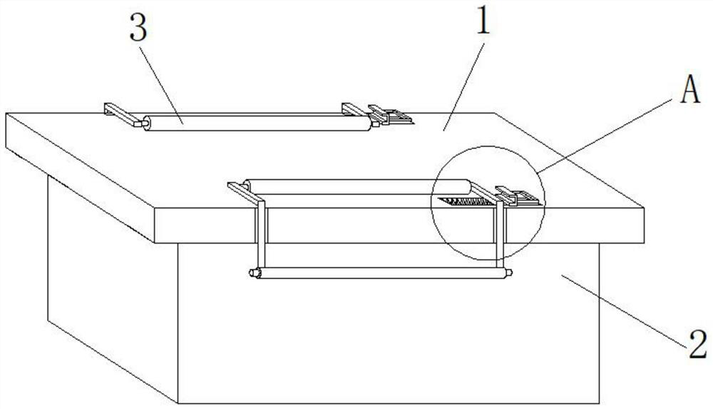
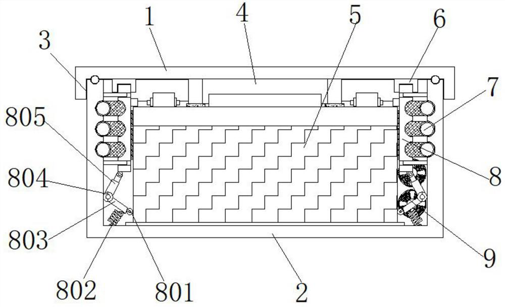
[0033] Example 1, such as Figure 1-7 As shown, when the battery assembly 5 needs to be put into the interior of the main body box 2, the card slot 301 is manually pulled so that the L-shaped bracket 303 leaves the inner side of the card slot 301, and then the two sets of L-shaped brackets 303 are manually opened downwards. , release the fixing effect on the cover plate 1, then open the cover plate 1, hold the handle on the battery assembly 5, and slowly put the battery assembly 5 into the inside of the main box 2, and when the battery assembly 5 enters the main box 2 , the outer side of the battery assembly 5 is in contact with the roller 801, and forces the connecting rod 803 and the lifting rod 805 to rotate around the hinge shaft 804. It is closely attached to the outside of the battery assembly 5, so that the battery assembly 5 is clamped and fixed.

Embodiment 2

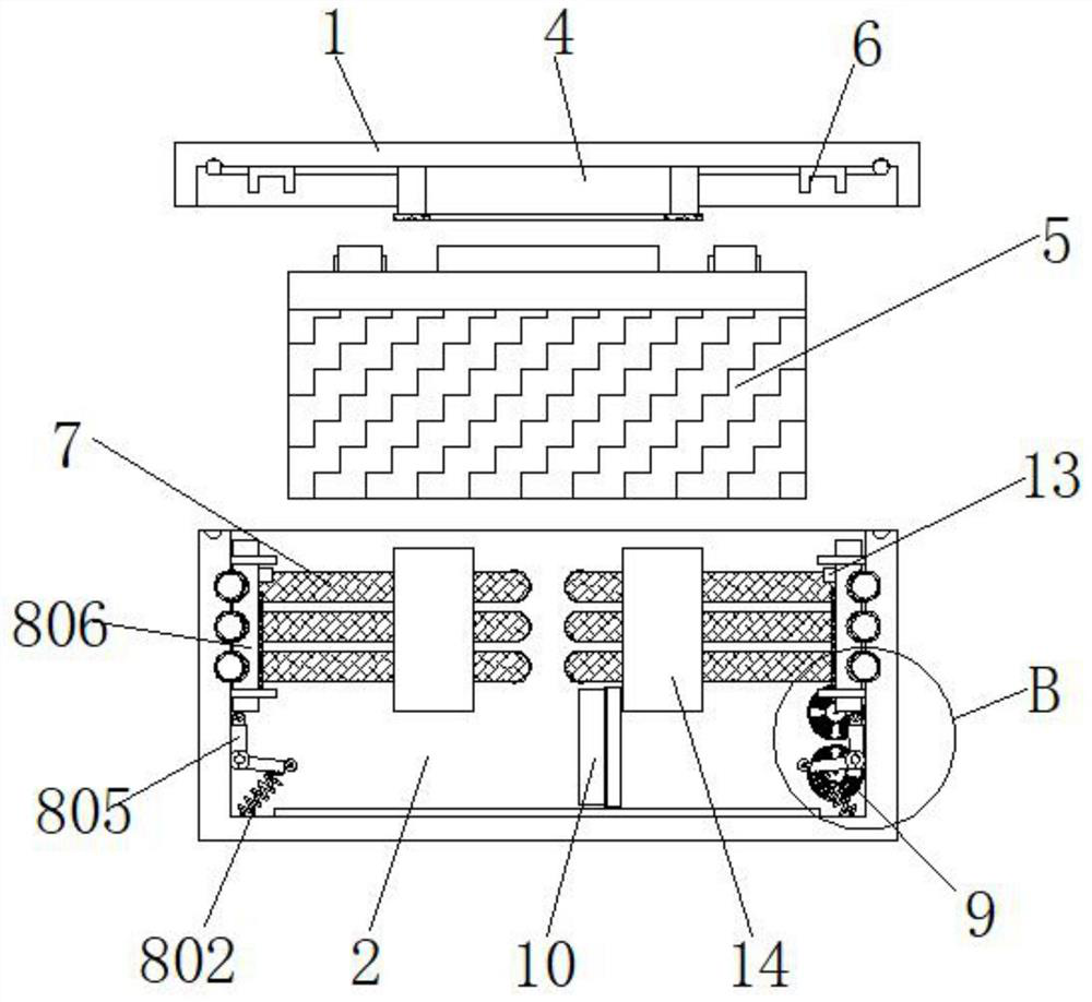
[0034] Example 2, such as figure 2 , 3 As shown in , 4, 6 and 7, when the new energy vehicle is used in summer, the water pump 16 and the fan 9 are controlled to start working through the external control panel, so that the coolant inside the coolant tank 15 enters into the three sets of heat exchange tubes 7 inside, and then flow back to the inside of the coolant tank 15 through the water pump 16, so that the coolant can circulate and use the coolant to absorb the heat inside the main body case 2, and the fan 9 makes the air inside the main body case 2 circulate in the battery It flows in the gap between the component 5 and the main box 2, that is, it flows around the battery component 5 and enters the interior of the installation compartment 11 from the air inlet 10, and then the fan 9 blows air into the battery component 5 and the main box 2 In the gap between them, the circulation of air is formed, and the heat absorption effect of the cooling liquid is correspondingly i...

Embodiment 3

[0035] Example 3, such as image 3 , 4 As shown in and 6, when the new energy vehicle is used in winter, the fan 9 and the electric heating tube 12 are controlled to start working through the external control panel, and the heat generated by the electric heating tube 12 is blown into the inside of the main body box 2 by the fan 9, and is surrounded by The air circulating in the main body box 2 brings heat to the periphery of the battery assembly 5 , thereby increasing the temperature of the air around the battery assembly 5 .

[0036] Working principle: when the battery pack 5 needs to be put into the main body box 2, manually pull the card slot 301 so that the L-shaped bracket 303 leaves the inner side of the card slot 301, and then manually open the two sets of L-shaped brackets 303 downwards , release the fixing effect on the cover plate 1, then open the cover plate 1, hold the handle on the battery assembly 5, and slowly put the battery assembly 5 into the inside of the m...


PUM


Abstract

The invention discloses a battery lock box for a new energy vehicle, which includes a main body box. One end of the main body box is provided with an installation compartment, and one side of the interior of the installation compartment is installed with a cooling liquid compartment. A water pump is installed on the top of one side, an electric heating tube is installed on the bottom of the installation compartment close to the water pump, a battery assembly is installed inside the main body box, and two group of fans. The present invention uses the main body box, the battery assembly, the heat exchange tube, the fan, the air inlet, the installation warehouse, the electric heating pipe, the fixing frame, the cooling liquid warehouse and the water pump to avoid the temperature being too high and affecting the battery assembly in summer. In winter, the electric heating tube can also be used to generate heat, and the fan can be used to blow heat into the interior of the main box to increase the temperature around the battery components, thereby ensuring the endurance of the battery components in winter.

Description

technical field [0001] The invention relates to the technical field of new energy vehicles, in particular to a battery lock box of a new energy vehicle. Background technique [0002] With the continuous development and progress of new energy vehicle technology, new energy vehicles have developed from short-distance scooters in the early stage to a variety of models today, from small cars, medium-sized cars to various types of urban SUVs, new energy vehicles are gradually replacing Fuel vehicles have become the mainstream development direction in the automotive field; the built-in battery packs of existing new energy vehicles are placed inside the lock box, which is convenient to use the lock box to protect the battery pack. [0003] The existing battery lock box can only protect the battery pack, and because the battery lock box is mostly a sealed box structure, the insulation effect on the temperature is poor. In the hot summer, the higher temperature It will be transmitte...

Claims


Application Information

Patent Timeline
Patent Type & Authority Patents(China)
IPC IPC(8): H01M50/204H01M50/233H01M50/242H01M50/24H01M50/258H01M10/613H01M10/61H01M10/625H01M10/657B60K1/04B60S5/06
CPCB60K1/04B60S5/06H01M10/61H01M10/613H01M10/625H01M10/657Y02E60/10
Inventor 徐中利
Owner SUZHOU ZHIRUI PHOTOELECTRIC MATERIAL TECH CO LTD
Why Eureka
Try Eureka