
Motor control device and method, and rotating motor

A motor control and rotating motor technology, applied in the direction of suppressing motor vibration control, electromechanical devices, and connecting with control/drive circuits, etc. Improve work performance, good vibration and noise reduction, and ease device loosening or damage

Pending Publication Date: 2020-11-24
GREE ELECTRIC APPLIANCES INC
View PDF0 Cites 1 Cited by
  • Summary
  • Abstract
  • Description
  • Claims
  • Application Information

AI Technical Summary

Problems solved by technology

[0004] The present invention aims at the problem that the noise reduction effect of the traditional noise reduction method is not obvious, the vibration of the motor cannot be alleviated, and the working performance of the motor is poor, and a motor control device, method and rotating motor are proposed. The motor control device, method and rotating motor can It achieves a good effect of vibration reduction and noise reduction, alleviates the loosening or damage of components caused by motor vibration, and improves the technical effect of the motor's working performance

Method used


Image

  • Motor control device and method, and rotating motor
  • Motor control device and method, and rotating motor
  • Motor control device and method, and rotating motor

Examples


Embodiment Construction

[0024] In order to make the object, technical solution and advantages of the present invention clearer, the present invention will be described more comprehensively through the following embodiments and in conjunction with the accompanying drawings. It should be understood that the specific embodiments described here are only used to explain the present invention, not to limit the present invention.

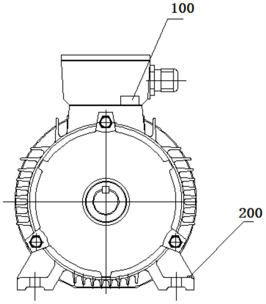
[0025] In one embodiment, see figure 1 , providing a motor control device, including a vibration sensor 200, a controller 100 and a peak clipping coil 300, the vibration sensor 200 is arranged on the motor, the peak clipping coil 300 is arranged on the side of the stator winding 1 away from the rotor 4 of the motor, the vibration sensor 200 and the peak-shaving coil 300 are both connected to the controller 100 . The vibration sensor 200 is used to detect the vibration of the motor to generate a vibration signal and transmit it to the controller 100. The controller 100 is used to...


PUM


Abstract

The invention relates to a motor control device and method, and a rotating motor. The motor control device comprises a vibration sensor, a controller and a peak clipping coil, wherein the vibration sensor is arranged on the motor; the peak clipping coil is arranged on one side, away from the rotor of the motor, of the stator winding; the vibration sensor and the peak clipping coil are connected with the controller; the vibration sensor is used for detecting vibration of the motor to generate a vibration signal and transmitting the vibration signal to the controller; the controller is used forgenerating a pulse signal according to the vibration signal and transmitting the pulse signal to the peak clipping coil; and the pulse signal is used for controlling the peak clipping coil to generatea magnetic field opposite to a harmonic field generated by a stator winding of the motor. According to the motor control device, the controller enables the peak clipping coil to generate a magnetic field opposite to the magnetic field generated by the stator winding in direction according to the vibration of the motor, a harmonic magnetic field generated by a stator winding can be counteracted, the magnetic resistance of a motor yoke part is increased, the magnetic density of a motor air gap is reduced, the vibration and noise reduction effects are good, the problem of device loosening or damage caused by motor vibration can further be relieved, and the working performance of the motor is improved.

Description

technical field [0001] The present application relates to the technical field of electrical equipment, in particular to a motor control device, a method and a rotating electrical machine. Background technique [0002] The main function of the motor is to generate driving torque, and it is widely used as a power source for electrical appliances or various machines. The motor will generate noise when it is working. The noise is caused by tangential force and radial force. The tangential electromagnetic force will generally cause torque fluctuations, which will further cause vibration noise, while the radial electromagnetic force will cause the stator to vibrate and transmit vibration to the structure. and radiate noise into the air. The higher the motor speed, the more obvious the vibration of the unit will be. In severe cases, it will cause violent shaking of the unit, loose connections, damage to seals, wear and failure of transmission parts and affect the normal operation ...

Claims


Application Information

Patent Timeline
IPC IPC(8): H02K11/20H02K11/21H02K3/46H02K3/12H02K11/30H02P23/04
CPCH02K3/12H02K3/46H02P23/04H02K11/20H02K11/21H02K11/30
Inventor 汤绍鸿刘振邦樊钊刘怡迪何景伦
Owner GREE ELECTRIC APPLIANCES INC
Learn More