
Cedar branch pruning device for forestry

A pruning device and fir tree technology, which is applied in the field of fir branch pruning devices for forestry, can solve the problems of inaccessibility and limited pruning height, and achieve the effect of labor-saving incision cracking, reducing water evaporation, and ensuring neatness

Inactive Publication Date: 2020-11-27
闫哲阶
View PDF5 Cites 1 Cited by
  • Summary
  • Abstract
  • Description
  • Claims
  • Application Information

AI Technical Summary

Problems solved by technology

A forestry branch pruning device, including a base, universal wheels, pull handles, a fixed box, a battery, a first installation box, a telescopic cylinder, a connecting rod, an L-shaped installation plate, a hook, a collection net bag, etc.; the fixed box, the first The installation boxes are fixed on the top of the base, the battery is fixed in the fixed box, the telescopic cylinder is fixed in the bottom of the first installation box, the side of the first installation box away from the fixed box is provided with a first through hole, the first installation box One inner side wall has a chute; however, the device has a limited trimming height and cannot reach taller branches

Method used


Image

  • Cedar branch pruning device for forestry
  • Cedar branch pruning device for forestry
  • Cedar branch pruning device for forestry

Examples


Embodiment 1

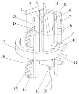
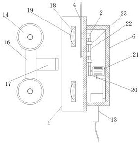
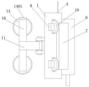
[0029] refer to Figure 1-4 , a forestry fir tree branch pruning device, comprising a vertically placed trough plate base 1, the trough plate base 1 includes two side guard plates and a middle plate, and the upper and lower ends of the two side guard plates are provided with Roller hole 18, the opposite side of the two side guards is provided with a roller driving box 7 near the side of the roller hole 18, and the roller driving box 7 is connected with a driving wheel 19 in rotation near the roller hole 18, one of the sides Two parallel vertical vertical plates 10 are fixed on the edge of the guard plate, and the same rotary shaft 9 is rotatably connected between the two vertical vertical plates 10, and a torsion spring 901 is sleeved in the middle of the rotary shaft 9, and the torsion spring The outer wall of 901 is sleeved with a crescent-shaped arc arm plate 11, and the end of the arc arm plate 11 away from the rotary shaft 9 is fixed with two parallel bearing fixing plate...

Embodiment 2

[0039] refer to figure 1 with Figure 5 , a forestry fir branch pruning device, compared with Embodiment 1, this embodiment also includes a tapered sawing board 24 with a triangular structure fixed to the tops of the two side guards, and the tapered sawing board 24 The oblique openings are all arranged in a knife-edge shape.

[0040] Working principle: When cutting upwards, it is changed to sawing, which saves more labor and avoids the incision from cracking, ensures the neatness of the incision, reduces the evaporation of water in the later stage and improves the survival rate.


PUM


Abstract

The invention belongs to the technical field of forestry equipment and particularly relates to a cedar branch trimming device for forestry. To solve the problem that an existing pruning tool cannot prune branches dozens of meters high, the following scheme is provided: the device comprises a groove-shaped plate seat which is vertically arranged, the groove-shaped plate seat comprises two side protection plates and a middle plate, roller holes are formed in the upper and lower ends of the two side protection plates, roller driving boxes are arranged on the sides, close to the roller holes, of the opposite sides of the two side protection plates correspondingly, driving wheels are rotatably connected to the positions, close to the roller holes, of the roller driving boxes correspondingly, two parallel vertical plates are fixed to the edge of one side protection plate, and the same rotating shaft is rotatably connected between the two vertical plates. When the device is used, the device can drive a plain-end knife to rapidly make contact with small branches outside tree trunks when rapidly rushing upwards, and strong kinetic energy is matched with sharp knife edge support to smoothlycut off side branches.

Description

technical field [0001] The invention relates to the technical field of forestry equipment, in particular to a forestry fir branch pruning device. Background technique [0002] Many trees need to be pruned every year to ensure scientific and reasonable growth. The traditional pruning method is to prune by climbing a ladder or tie a knife with a bamboo pole. For example, pruning by climbing a ladder is difficult because of the complex environment in the woods. The moving ladder caused not only laborious but also time-consuming in the process of pruning; for pruning by binding knives on bamboo poles, because it is simply to bind tools such as knives on bamboo poles, it is necessary to cut off many thicker branches. It is a very strenuous thing. After a long time of operation, it is easy to cause blisters in the palm of the hand, and it is easy to cause fatigue in the arms and shoulders. [0003] A pruning device disclosed in Chinese Patent No. CN201920869480.3 after retrieval....

Claims


Application Information

Patent Timeline
Patent Type & Authority Applications(China)
IPC IPC(8): A01G3/08
CPCA01G3/08
Inventor 闫哲阶
Owner 闫哲阶
Learn More