

Desublimation device suitable for iodine refining and using method thereof
A desublimator and purpose technology, applied in the field of iodine-refined desublimer device, can solve the inconvenience of containing a small amount of iodine, etc., and achieve the effects of avoiding unclean cleaning, ensuring normal operation, and improving the practicability of equipment
- Summary
- Abstract
- Description
- Claims
- Application Information
AI Technical Summary
Problems solved by technology
Method used
Image

Examples
Embodiment 1
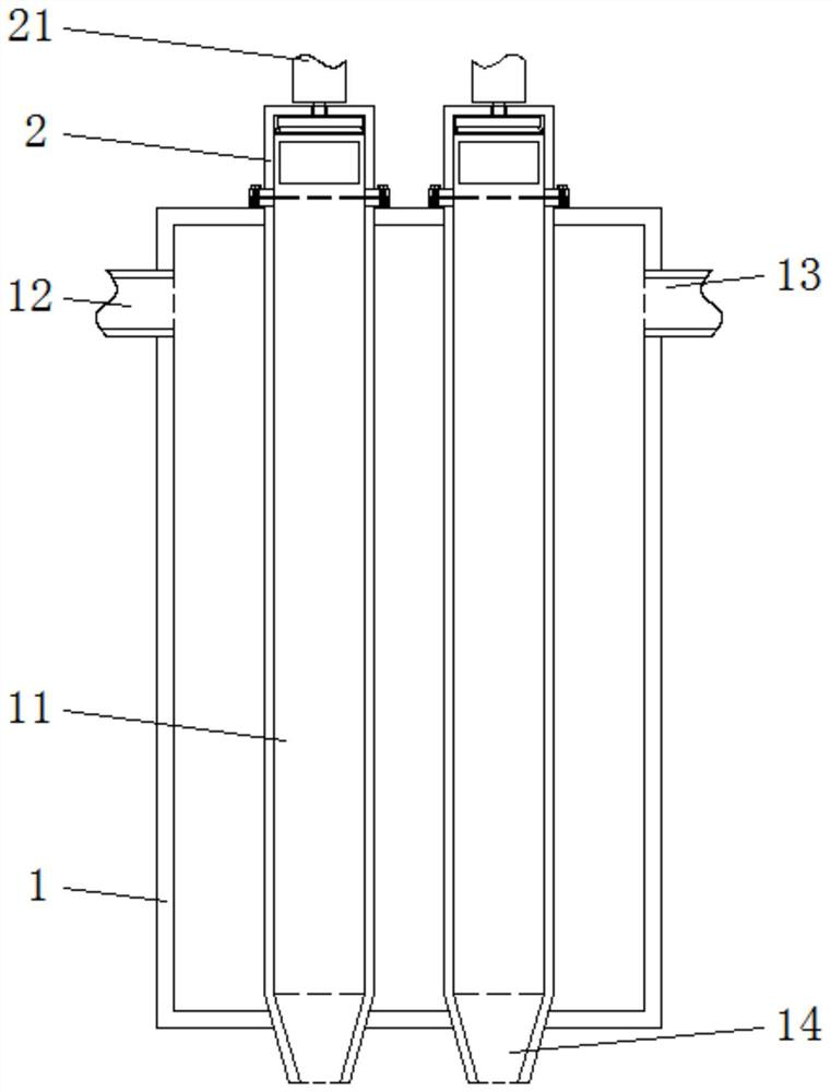
[0038]A desublimer device suitable for iodine refining and its use method, comprising a casing 1, a sealing cover 2, an exhaust pipe 4, a first support block 15, screw holes 16 and a limiting groove 45, the outer wall of one side of the casing 1 is inserted An oil inlet pipe 12 is connected and installed, and an oil discharge pipe 13 is inserted and installed on the outer wall of the shell 1 away from the oil inlet pipe 12 . Through the oil inlet pipe 12 and the oil discharge pipe 13, the circulation of the low-temperature heat transfer oil inside the casing 1 is ensured, and heat accumulation is avoided. After the low-temperature heat transfer oil is pressurized by the oil pump, it enters the interior of the shell 1 through the oil inlet pipe 12, and can be discharged through the oil discharge pipe 13 to ensure the internal temperature circulation of the shell 1, thereby achieving the purpose of reducing the internal temperature of the sealing cover 2. The iodine vapor passes ...
Embodiment 2
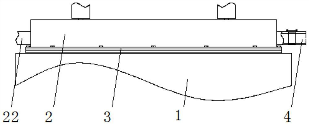
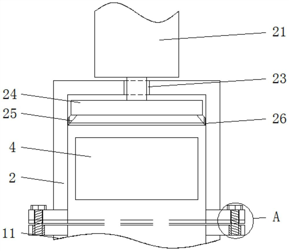
[0044] A desublimator device suitable for iodine refining and its use method, comprising a casing 1, a sealing cover 2, an exhaust pipe 4, a first support block 15, screw holes 16 and a limit groove 45, and the inside of the casing 1 is symmetrically inserted Condensation chamber 11 is installed, and the outer wall side of the upper end of condensation chamber 11 is provided with sealing cover 2, and the outer wall of sealing cover 2 side is inserted and installed with intake pipe 22, and the outer wall of sealing cover 2 away from intake pipe 22 is inserted and installed with exhaust pipe. 4. An installation groove 41 is opened on one side of the outer wall of the upper end of the exhaust pipe 4 . The installation slot 41 is used for placing the connection board 42 . A connecting plate 42 is movably installed inside the installation groove 41, and a support plate 44 is installed on the outer wall of one end of the connection plate 42 through the installation groove 41, and a ...
PUM
 Abstract
Description
Claims
Application Information