
Assembly comprising shoveling and milling machine arm frame and milling and digging device

A milling and milling machine technology, which is applied to mining equipment, earthwork drilling, tunnels, etc., can solve the problems of reducing the frequency of blasting, high construction safety risks, and slow progress, and achieves the increase and expansion of the working range and variable angle Applicable occasions, reduce the effect of severe vibration

Pending Publication Date: 2020-11-27
CHINA RAILWAY CONSTR HEAVY IND
View PDF0 Cites 1 Cited by
  • Summary
  • Abstract
  • Description
  • Claims
  • Application Information

AI Technical Summary

Problems solved by technology

[0004] The blasting excavation method using partition blasting has high requirements for blasting quality control, difficulty in protecting the surrounding infrastructure, high construction safety risks, high construction costs, and slow progress. At the same time, there will be varying degrees of under-excavation in blasting, which will affect subsequent construction. The method of adding a milling head to the machine can effectively complete the section cleaning after blasting and trim the contour. At the same time, some areas with low rock strength can be milled separately to reduce the frequency of blasting. However, the modified milling head The working capacity and milling range are limited by the parameters of the excavator itself, the milling range is small, and it cannot adapt to the milling conditions in areas with high strength rocks

Method used


Image

  • Assembly comprising shoveling and milling machine arm frame and milling and digging device
  • Assembly comprising shoveling and milling machine arm frame and milling and digging device
  • Assembly comprising shoveling and milling machine arm frame and milling and digging device

Examples


Embodiment 1

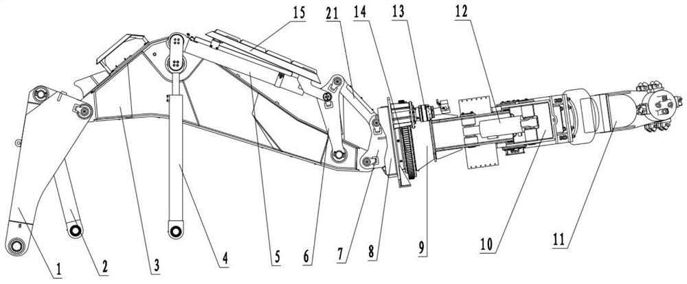
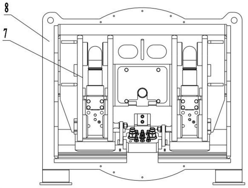
[0030] see Figure 1 ~ Figure 4 , an assembly comprising a shovel milling machine arm frame and a milling and digging device, the quick change device 7 of the shovel milling machine arm frame is connected to the base 8 of the milling and digging device;

[0031] The arm frame of the scraper milling machine includes a boom 1, a boom cylinder 2, a stick arm 3, a stick cylinder 4, a rocker 6, a connecting rod 21, a rocker cylinder 5, and a quick change device 7; one end of the boom 1 is connected to The frame of the scraper milling machine is rotatably connected, and the other end is rotatably connected to the first end of the stick arm 3 through a pin shaft; the second end of the stick arm 3 is rotatably connected to the quick change device 7 through a pin shaft; one end of the boom cylinder 2 It is hinged with the frame, and the other end is hinged with the boom 1; one end of the stick cylinder 4 is hinged with the frame, and the other end is hinged with the stick arm 3; one en...


PUM


Abstract

The invention provides an assembly comprising a shoveling and milling machine arm frame and a milling and digging device. A quick-changing device of the shoveling and milling machine arm frame is connected with the base of the milling and digging device; the milling and digging device comprises the base, a milling and digging arm, a milling and digging headstock, a milling and digging head and a stabilizing oil cylinder; the base is connected with one end of the milling and digging arm through a rotary support; the other end of the milling and digging arm is rotatably connected with the milling and digging headstock; the milling and digging head is mounted on the milling and digging headstock; one end of the stabilizing oil cylinder is rotatably connected with the milling and digging arm;and the other end of the stabilizing oil cylinder is rotatably connected with the milling and digging headstock. In the assembly, the rotary support is additionally arranged in the milling and diggingdevice to replace traditional bolt connection, so that the working range and the variable angle of the milling and digging head are greatly increased, and the usable occasions of the assembly are expanded. The quick-changing device is provided with an independent quick-changing oil cylinder and a quick-changing pin, so that the milling and digging device is quickly detached, a bucket and other types of construction equipment are mounted; and during the entire process, the quick-changing oil cylinder is adopted to lock the milling and digging device, so that the equipment universality is enhanced while lowering the manual labor intensity.

Description

technical field [0001] The invention relates to the technical field of tunnel construction equipment, in particular to an assembly including an arm frame of a scraper milling machine and a milling and digging device. Background technique [0002] The drill and blast method is often used in the tunnel excavation process, but the foundation settlement and environmental pollution caused by the drill and blast method during the construction process are relatively large, and are restricted by the natural environment. For areas where the tunnel depth is shallow and there are buildings on the ground, For example, roads and bridges, residences and iron towers, etc., the drilling and blasting method construction cannot completely guarantee the safety of ground buildings, and at the same time, closed construction is required, which is not conducive to the operation of ground traffic and has a great impact on the safety of surrounding personnel. In order to ensure the safety of excavati...

Claims


Application Information

Patent Timeline
Patent Type & Authority Applications(China)
IPC IPC(8): E21D9/10
CPCE21D9/1006E21D9/104E21D9/1093
Inventor 刘飞香张海涛蔡岗础王知讯郭超峰潘国智张贤福谷开
Owner CHINA RAILWAY CONSTR HEAVY IND
Learn More