
Diesel engine and flame glow plug thereof

A diesel engine and glow plug technology, applied in engine components, engine starting, machine/engine, etc., can solve the problems of short heating time, slow heating of heating elements, insufficient temperature, etc., to increase heating time and smooth cold start , the effect of promoting gasification

Active Publication Date: 2020-11-27
BEIJING INSTITUTE OF TECHNOLOGYGY
View PDF14 Cites 6 Cited by
  • Summary
  • Abstract
  • Description
  • Claims
  • Application Information

AI Technical Summary

Problems solved by technology

There are two disadvantages in the currently used electric heating ignition method: on the one hand, it consumes a lot of electric power, and the performance of the on-board power supply is also greatly reduced in a low-temperature environment. The power provided by the thermal plug is small, and since the method of directly heating the heating preheating element depends on the resistance of the heating element itself, the temperature rise efficiency is low, resulting in problems such as slow heating of the heating element and insufficient temperature; on the other hand, No guide device is added in the diesel flow channel of the existing glow plug, so that the heating time of the heating element of the diesel is shorter, the gasification level of the diesel is poor, and the combustion heating effect is not good
[0004] Therefore, the existing glow plug cannot guarantee the normal cold start of the diesel engine under extremely cold conditions

Method used


Image

  • Diesel engine and flame glow plug thereof
  • Diesel engine and flame glow plug thereof
  • Diesel engine and flame glow plug thereof

Examples


Embodiment Construction

[0029] The present invention will be described in detail below with reference to the accompanying drawings and examples.

[0030] In the present invention, extremely cold conditions refer to occasions where the ambient air temperature is equal to or lower than -32°C.

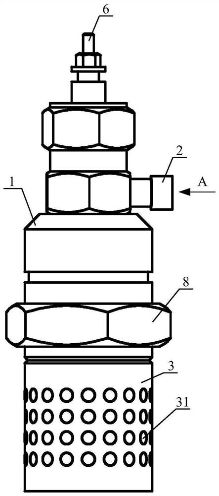
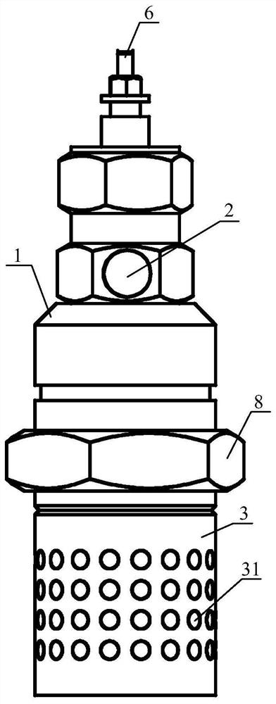
[0031] The invention provides a flame glow plug for a diesel engine, such as figure 1 with figure 2 As shown in the structure, the flame glow plug includes a housing 1, an oil inlet nozzle 2, a flame cover 3, an electromagnetic induction heating element 4, an electromagnetic induction coil 5 and an electrode 6;

[0032] The top of the housing 1 is provided with an electrode 6 for connecting to a power supply, and the bottom is provided with a cavity with an opening; the housing 1 is the basic component of the entire flame glow plug, and the top of the housing 1 is closed and the bottom is open;

[0033] The oil inlet nozzle 2 is fixedly installed on the outside of the housing 1 and communicates with the top o...


PUM


Abstract

The invention discloses a diesel engine and a flame glow plug thereof. The flame glow plug comprises a shell, an oil inlet nozzle, a flame cover, an electromagnetic induction heating element, an electromagnetic induction coil and an electrode; the electrode is arranged at the top end of the shell, and a cavity is formed in the bottom of the electrode; the oil inlet nozzle is fixedly installed on the outer side of the shell and communicates with the top of the cavity; the flame cover is fixedly connected with the bottom end of the shell and provided with a plurality of ventilation holes; the electromagnetic induction heating element is fixedly installed in the cavity, and the bottom end of the electromagnetic induction heating element protrudes out of the shell and extends into the flame cover; a gasification flow guide channel is formed between the shell and the electromagnetic induction heating element and is used for guiding, heating and gasifying diesel oil entering the cavity; theelectromagnetic induction coil is of a spiral structure, is installed in the gasification flow guide channel, is electrically connected with the electrode and is used for forming an electromagnetic field; and a mixed gas cavity is formed in the flame cover. The flame glow plug can guarantee normal cold start of the diesel engine under the extremely cold condition.

Description

technical field [0001] The invention relates to the technical field of an engine cold start assist system, in particular to a diesel engine and a flame glow plug thereof. Background technique [0002] When a diesel engine is started in a low-temperature environment, due to reasons such as low speed, high air leakage and high heat transfer loss, the environment in the cylinder cannot reach the spontaneous combustion conditions of diesel spray at the time of compression top dead center, resulting in unstable combustion , or even a misfire, causing difficulty in starting the diesel engine. The cold start problem of diesel engine is one of the main reasons that limit its application field. In order to improve the cold start performance of a diesel engine in a low temperature environment, it is an effective method to add a flame glow plug at the front end of the intake manifold of the diesel engine. A small amount of diesel is burned through the flame glow plug to preheat the a...

Claims


Application Information

Patent Timeline
Patent Type & Authority Applications(China)
IPC IPC(8): F02N19/06F02N19/08
CPCF02N19/06F02N19/08
Inventor 刘福水王东方黎一锴史中杰
Owner BEIJING INSTITUTE OF TECHNOLOGYGY
Learn More