Outdoor gateway equipment installation outer box for communication power construction

A technology for equipment installation and power construction, applied in the substation/distribution device casing, substation/switch layout details, electrical components, etc., can solve problems such as short circuit of the box, entry into the inside of the box, and line damage, etc., to achieve good protection , Ease of installation and maintenance

Inactive Publication Date: 2020-11-27
陈建明
View PDF1 Cites 0 Cited by
  • Summary
  • Abstract
  • Description
  • Claims
  • Application Information

AI Technical Summary

Problems solved by technology

[0003] In the Chinese utility model patent document with the publication number CN205960477U, a new type of safety distribution box is disclosed, which is locked through the inner box door after the professional electrician completes the wiring installation operation, and can observe the leakage protectors through the partition window According to the operating conditions of the operation, the power transmission, power failure, leakage test and other operations are ca

Method used


Image

  • Outdoor gateway equipment installation outer box for communication power construction
  • Outdoor gateway equipment installation outer box for communication power construction
  • Outdoor gateway equipment installation outer box for communication power construction

Examples


Embodiment 1

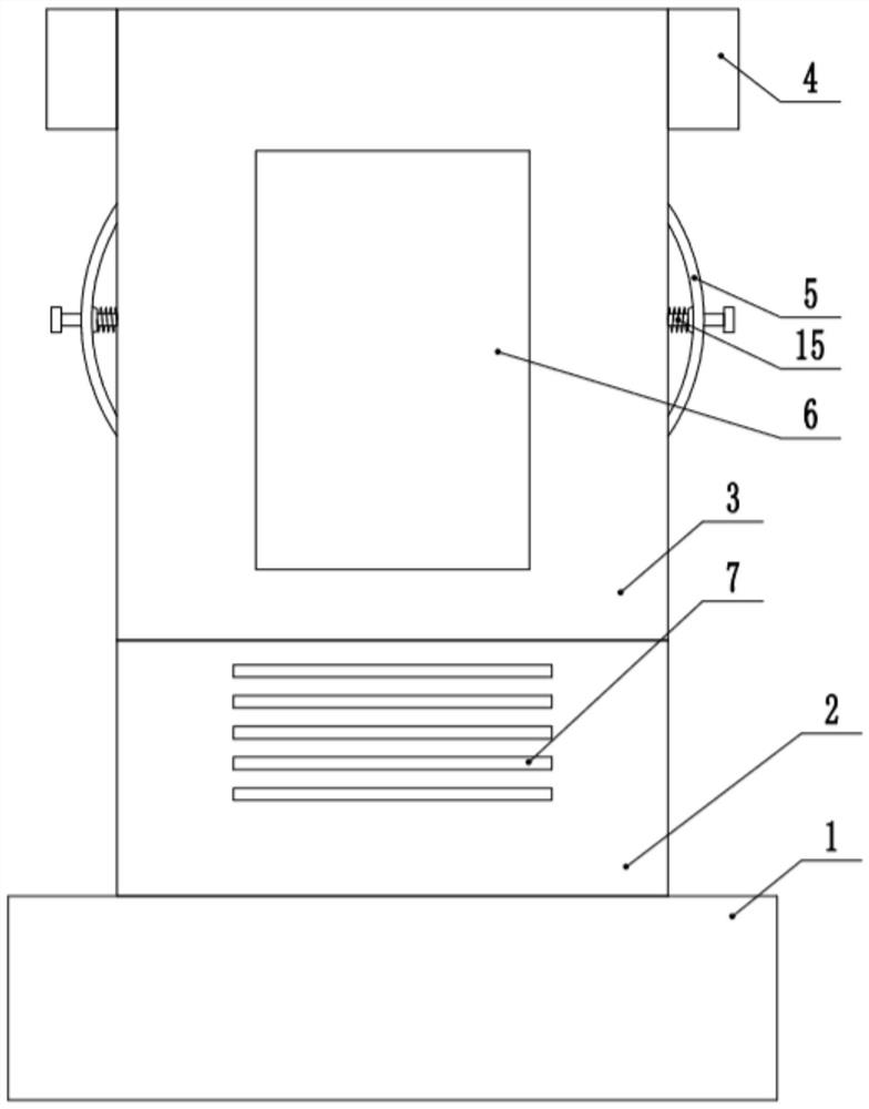
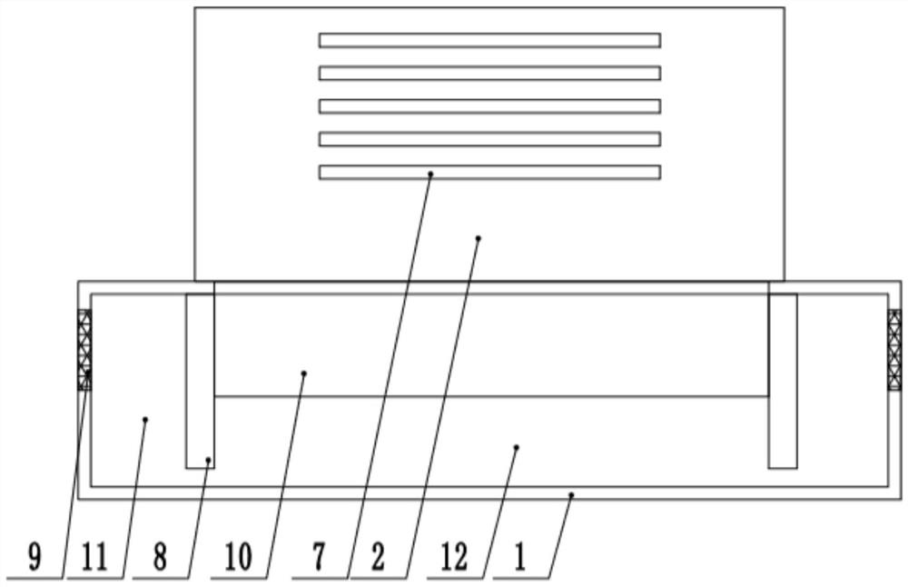
[0026] see Figure 1-6 An outer box for installing outdoor gateway equipment for communication power construction users, including a bottom box 1, the top of the bottom box 1 is fixedly connected to the lower box 2, the top of the lower box 2 is provided with an upper box 3, and the top of the upper box 3 Both sides of the top are fixedly connected to the exhaust hood 4, the inside of the exhaust hood 4 is fixedly connected to the induced draft fan, the lower box 2 is provided with an air intake mechanism, the bottom box 1 is equipped with a floating water sealing mechanism, and the two ends of the top of the lower box 2 Both are fixedly connected with the inner fixing plate 16, and both sides of the upper box body 3 are fixedly connected with the handle 5, and the handle 5 is connected with a locking device 15.

[0027] Described air intake mechanism comprises the slot 27 that is opened in lower box body 2 inside, and the outside of lower box body 2 is provided with a plurali...

Embodiment 2

[0035] see Figure 1-6 , The other content of this embodiment is the same as that of Embodiment 1, the difference is that: the upper box body 3 is provided with an observation port 6, and the observation port 6 is fixedly connected with an acrylic plate, and the acrylic plate is a transparent plate.

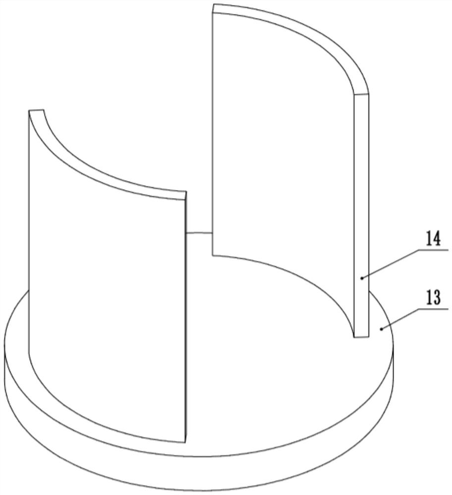
[0036] In the implementation process of the present invention, when in normal use, the induced draft fan is started, and the outside air enters the upper box body 3 and the lower box body 2 from the air inlet 7, and is discharged after the heat is taken away to realize heat dissipation. , water enters the bottom box 1, and the floating plate 13 floats up with the rise of the water level to drive the sealing plate 14 to move up to seal the air inlet 7, thereby effectively avoiding the problem of internal water ingress caused by the box body being flooded.


PUM


Abstract

The invention discloses an outdoor gateway equipment installation outer box for communication power construction, and relates to the field of communication power. The box comprises a bottom box. The top of the bottom box is fixedly connected with a lower box body. The top end of the lower box body is sleeved with an upper box body. The two sides of the top of the upper box body are fixedly connected with exhaust hoods. An induced draft fan is fixedly connected in the exhaust hood. An air inlet mechanism is arranged on the lower box body. A floating water sealing mechanism is arranged in the bottom box. The two ends of the top of the lower box are fixedly connected with inner fixing plates. Handles are fixedly connected to the two sides of the upper box body. The handle is connected with alocking device. By arranging the floating water sealing mechanism, water can be prevented from entering the mounting box due to accumulated water on the ground, the mounting box is well protected, hotair in the box body can be discharged by arranging the air inlet mechanism, fixed mounting and overall separation between the upper box body and the lower box body can be achieved by arranging the locking device, and mounting and maintenance are facilitated.

Description

technical field [0001] The invention relates to the field of communication power, in particular to an outer box for installing outdoor gateway equipment for communication power construction. Background technique [0002] In the process of power construction, a variety of power accessories and power facilities need to be used, and the distribution box is an indispensable power facility in power construction. The distribution box has the characteristics of small size, easy installation, special technical performance, fixed position, unique configuration function, not limited by the site, widely used, stable and reliable operation, high space utilization rate, less land occupation and environmental protection effect. The distribution box is a widely used transmission and distribution equipment for power transmission and distribution equipment, accounting for about 30% of all equipment. significant contribution. The distribution box has the characteristics of small size, easy ...

Claims


Application Information

Patent Timeline
IPC IPC(8): H02B1/46H02B1/56H02B1/28H02B1/48
CPCH02B1/28H02B1/46H02B1/48H02B1/565
Inventor 陈建明
Owner 陈建明
Why Eureka
Try Eureka