A high-performance stator permanent magnet bearingless motor

A bearingless motor and permanent magnet technology, applied in the direction of electromechanical devices, electrical components, electric components, etc., can solve the problems of poor heat dissipation effect of bearingless motors, poor performance of bearingless motors, etc., to solve the problem of poor heat dissipation , Improve the cooling effect, improve the cooling effect

Active Publication Date: 2022-01-28
HUAIYIN INSTITUTE OF TECHNOLOGY
View PDF5 Cites 1 Cited by
  • Summary
  • Abstract
  • Description
  • Claims
  • Application Information

AI Technical Summary

Problems solved by technology

[0006] The problem solved in one aspect of the present invention is: how to solve the problem of poor performance of the bearingless motor; through the use of the isolation ring and the conduit, the bearings at both ends of the motor body can be canceled to avoid contact with the bearing when the rotating column rotates. Friction is generated between them to achieve the purpose of improving the performance of the bearingless motor; the rotating column runs through the interior of the spacer ring near the middle, and several conduits are fixedly connected to the inner surface of the second connecting collar so that the rotating column does not contact the spacer ring when it rotates. Direct contact, the rotor core, stator core and stator windings generate the first heat when they work, through the rotation of several heat dissipation fan blades, the first heat is transmitted to the outside of the motor body through the heat dissipation net, which can effectively improve the working efficiency of the rotor , so as to improve the performance of the motor body, and solve the problem of poor performance of the bearingless motor in the existing scheme
[0007] The problem solved by another aspect of the present invention is: how to solve the problem of the poor heat dissipation effect of the bearingless motor; through the cooperative use of the first radiating pipe, the second radiating pipe, the third radiating pipe and the conduit, it can effectively Improve the heat dissipation effect of the bearingless motor; the second heat is generated when the rotating column is working, and the motor makes the first transmission column, the second transmission column and the third transmission column rotate, and the first transmission column, the second transmission column and the third transmission column The rotation of the column drives the first heat conduction fan blade, the second heat conduction fan blade and the third heat conduction fan blade to rotate, and the three groups of the first heat conduction fan blade, the second heat conduction fan blade and the third heat conduction fan blade rotate to make the first heat pipe The air in the second heat dissipation pipe and the third heat dissipation pipe circulates outward, so that a pressure difference is generated in the first heat dissipation pipe, the second heat dissipation pipe and the third heat dissipation pipe; the pressure difference is transmitted to the conduit through the second connecting elbow and the first connecting elbow Inside, the second heat is absorbed into several pipes through the pressure difference, the second heat enters the first connecting elbow and the second connecting elbow through the pipes, and passes through the first heat dissipation pipe, the second heat dissipation pipe and the third heat dissipation pipe The pipe is discharged outside the motor body, which can eliminate the influence of the second heat on the work of the rotating column, and can effectively improve the heat dissipation effect inside the motor body, and solve the problem of poor heat dissipation effect of the bearingless motor in the existing scheme

Method used


Image

  • A high-performance stator permanent magnet bearingless motor
  • A high-performance stator permanent magnet bearingless motor
  • A high-performance stator permanent magnet bearingless motor

Examples


Embodiment Construction

[0033] The technical solutions of the present invention will be clearly and completely described below in conjunction with the embodiments. Apparently, the described embodiments are only some of the embodiments of the present invention, not all of them. Based on the embodiments of the present invention, all other embodiments obtained by persons of ordinary skill in the art without creative efforts fall within the protection scope of the present invention.

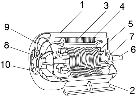
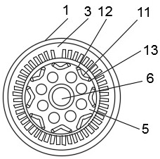
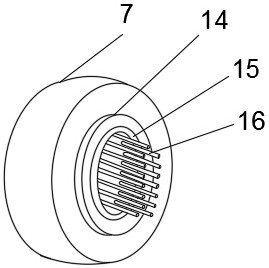
[0034] Such as Figure 1-6 As shown, a high-performance stator permanent magnet bearingless motor includes a motor body 1 and an isolating ring 7, and the isolating ring 7 is fixedly installed on the inner surface of the motor body 1 near one side, and the motor body 1 A stator core 3, a stator winding 4, a rotor core 5 and a rotating column 6 are fixedly installed inside, the stator winding 4 and the rotor core 5 are both located inside the stator core 3, and the stator winding 4 is located in the stator core 3 and the ro...


PUM


Abstract

The invention discloses a high-performance stator permanent magnet bearing-less motor. Through the cooperative use of an isolation ring and a conduit, the bearings at both ends of the motor body can be eliminated to avoid friction between the rotary column and the bearings when rotating, thereby achieving improved performance. The purpose of bearingless motor performance; the rotating column penetrates the inside of the isolation ring near the middle position, and several conduits are fixedly connected to the inner surface of the second connecting collar, so that the rotating column does not directly contact with the isolation ring when rotating, and the rotor core, The stator core and stator winding generate the first heat when working. Through the rotation of several cooling fan blades, the first heat is transmitted to the outside of the motor body through the heat dissipation network; through the first heat dissipation pipe, the second heat dissipation pipe and the third heat dissipation pipe. The combined use of heat pipes and conduits can effectively improve the heat dissipation effect of the bearingless motor; various aspects disclosed in the present invention can solve the problem of poor performance of the bearingless motor and the problem of poor heat dissipation effect of the bearingless motor.

Description

technical field [0001] The invention relates to the technical field of motors, in particular to a high-performance stator permanent magnet bearingless motor. Background technique [0002] The bearingless motor is based on the similarity of the principle of electromagnetic force generated by the magnetic bearing and the motor. The winding that generates the radial force in the magnetic bearing is installed on the stator of the motor, and the independent control of the motor torque and radial suspension force is realized through decoupling control. . Bearingless motors have all the advantages of magnetic levitation magnetic bearings, and require maintenance-free, long-life operation. The transmission of sterile, pollution-free, toxic and harmful liquids or gases is a typical application of bearingless motors; [0003] Corrosive chemical liquids are used in processing processes such as etching, plate making, cleaning or polishing. The quality of products depends largely on the...

Claims


Application Information

Patent Timeline
Patent Type & Authority Patents(China)
IPC IPC(8): H02K9/06H02K9/04H02K9/00H02K5/20
CPCH02K9/06H02K9/04H02K9/00H02K5/20
Inventor 朱为国乐倩云叶小婷武莎莎张涛鲁庆丁卫红
Owner HUAIYIN INSTITUTE OF TECHNOLOGY
Why Eureka
Try Eureka