Camera with dustproof function for agricultural machinery

A technology for agricultural machinery and cameras, applied in the agricultural field, can solve the problems of narrowing the visible range of agricultural dust-proof cameras and the like

Active Publication Date: 2020-11-27
东台市一是一科技有限公司
View PDF11 Cites 3 Cited by
  • Summary
  • Abstract
  • Description
  • Claims
  • Application Information

AI Technical Summary

Problems solved by technology

[0003] Since the agricultural dust-proof camera is installed around the crop land for monitoring work, and when the crop land is irrigated by rotating the irrigator, it is easy to appear that the rotating irrigator close to the agricultural dust-proof camera will spread the water around, and the water will Most of the water sprinkled on the camera mirror and sprayed by the rotating irrigator comes from streams and rivers, so that impurities such as aquatic plant fragments in the water will adhere to the mirror surface together, resulting in the reduction of the visual range of the agricultural dust-proof camera

Method used


Image

  • Camera with dustproof function for agricultural machinery
  • Camera with dustproof function for agricultural machinery
  • Camera with dustproof function for agricultural machinery

Examples


Embodiment 1

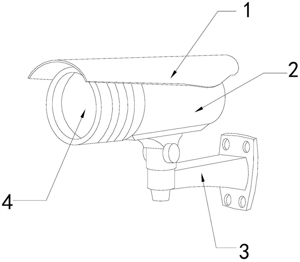
[0026] For example figure 1 -example Figure 5 Shown:

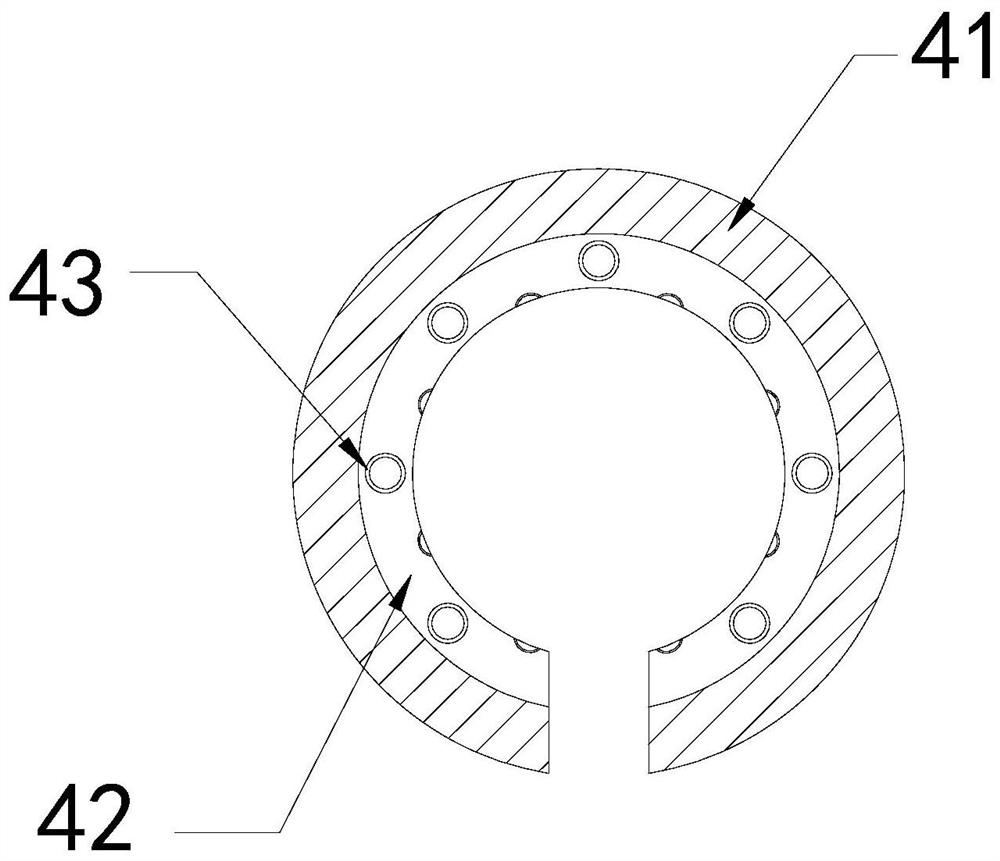
[0027] The present invention provides a camera with dustproof function for agricultural machinery, the structure of which includes a dustproof cover 1, a body 2, a support rod 3, and a front lens 4. The dustproof cover 1 is embedded and fixed at the upper end of the body 2, The front end of the body 2 is movably engaged with the support rod 3, and the front lens 4 is an integrated structure with the body 2; the front lens 4 includes an outer frame 41, an inner frame 42, and a water inlet 43. The frame 42 is fixed on the inner side of the outer frame 41 , and the water inlet 43 and the inner frame 42 are integrated.

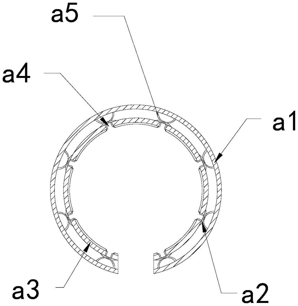
[0028] Wherein, the inner frame 42 includes an outer ring a1, a blocking block a2, an inner ring a3, a water outlet a4, and an elastic frame a5, the blocking block a2 is connected with the elastic frame a5, and the water outlet a4 and the inner ring a3 are Integrated structure, the elastic frame a5 is embe...

Embodiment 2

[0034] For example Figure 6 -example Figure 8 Shown:

[0035] Wherein, the water inlet 43 includes a frame c1, a force rod c2, a rebound bar c3, and an intercepting mechanism c4. Between the mechanism c4 and the force rod c2, the interception mechanism c4 is engaged with the force rod c2. The interception mechanism c4 has an isosceles trapezoidal structure, and the thrust generated by the water flow on the interception mechanism c4 can make the interception mechanism c4 Sliding down along the force rod c2, so that the water flow can be discharged through the gap between the intercepting mechanism c4 and the inner wall of the frame c1.

[0036] Wherein, the intercepting mechanism c4 includes a block c41, an upper extension frame c42, and a discharge mechanism c43. The upper extension frame c42 is in clearance fit with the discharge mechanism c43, and the discharge mechanism c43 is embedded in the upper end of the block c41. The side surface of the block c41 has an internal...


PUM


Abstract

The invention discloses a camera with a dustproof function for agricultural machinery. The camera structurally comprises a dustproof cover, a camera body, a supporting rod and a front lens, and the dustproof cover is embedded and fixed at the upper end of the camera body; the camera body is movably clamped with the front end of the supporting rod; and the front lens and the camera body are of an integrated structure. Part of water sprayed on the front lens can be guided into the inner frame through the water inlet; water in the inner frame is used for generating pushing force on the stress plate on the stop block; the stress plate can drive the stop block to shrink inwards; and therefore, moisture in the inner frame is kept, the front lens is provided with a water inlet and a water outletand can be discharged outwards through the water outlet, so that aquatic plant fragments attached to the outer surface of the front lens can be flushed away, an intercepting mechanism can contract outwards through thrust generated by water to the intercepting mechanism, the water can enter the space between the intercepting mechanism and the inner wall of the frame body, and the fragments in the water can be intercepted through the block body.

Description

technical field [0001] The invention relates to the field of agriculture, in particular to a video camera with dustproof function for agricultural machinery. Background technique [0002] The agricultural dust-proof camera is mainly used to monitor large-scale crop land. It can record the visible range 24 hours through the camera, and the video can be transmitted to the indoor display screen, so that the staff can monitor the crops. Observing the condition of cultivated land, based on the above description, the inventors found that the existing camera with dustproof function for agricultural machinery mainly has the following deficiencies, for example: [0003] Since the agricultural dust-proof camera is installed around the crop land for monitoring work, and when the crop land is irrigated by rotating the irrigator, it is easy to appear that the rotating irrigator close to the agricultural dust-proof camera will spread the water around, and the water will Most of the water...

Claims


Application Information

Patent Timeline
IPC IPC(8): H04N5/225
CPCH04N23/52H04N23/57H04N23/51
Inventor 黄佳彬
Owner 东台市一是一科技有限公司
Why Eureka
Try Eureka