
Prober

A probe station and probe technology, applied in the field of probe station, can solve the problem of not being provided, and achieve the effects of eliminating stray capacitance, reducing the influence of external noise, and suppressing current leakage

Pending Publication Date: 2020-11-27
NIHON MICRONICS
View PDF7 Cites 1 Cited by
  • Summary
  • Abstract
  • Description
  • Claims
  • Application Information

AI Technical Summary

Problems solved by technology

However, the probe stations disclosed in these patent documents 1 and 2 are probe stations for inspecting semiconductor devices that exist alone, and are not probe stations for inspecting semiconductor devices while maintaining the state of the wafer. How to maintain the accuracy of the state of the wafer well characterizes semiconductor devices with electrodes on both front and back sides, does not provide any insight

Method used


Image

  • Prober
  • Prober
  • Prober

Examples


Embodiment Construction

[0053] Hereinafter, the present invention will be described using the drawings, but of course the probe station of the present invention is not limited to the illustrated probe station.

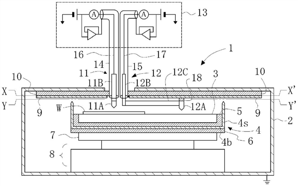
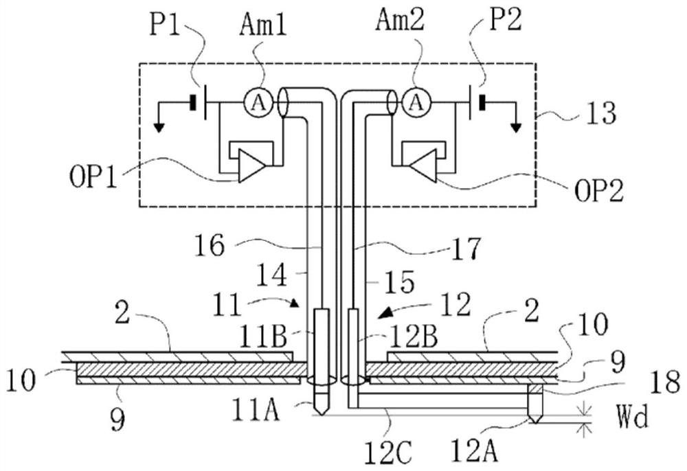
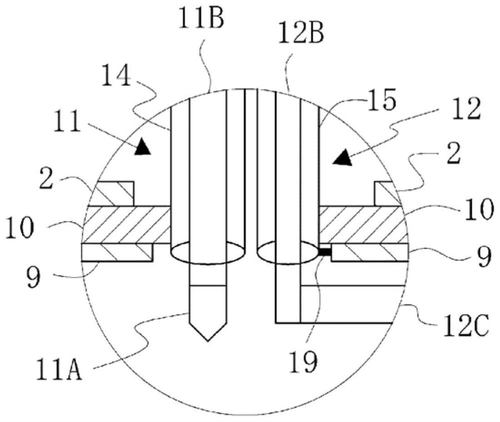
[0054] figure 1 It is a partial front sectional view showing an example of the probe station of the present invention. exist figure 1 Among them, 1 is the probe station of the present invention, 2 is the frame body, 3 is the chuck stage, and 4 is the chuck cover conductor. The chuck cover conductor 4 has a bottom conductor 4b and a side conductor 4s, and its upper surface is open. 5 is an insulator disposed between the chuck stage 3 and the chuck cover conductor 4 . As shown in the figure, the height of the side conductor 4s of the chuck cover conductor 4 is set so that the top end thereof is higher than the upper surface of the chuck stage 3, and the chuck stage 3 is embedded with the insulator 5 into the The space surrounded by the bottom conductor 4b and the side conductor 4s of the ch...


PUM


Abstract

The present invention addresses the problem of providing a prober with which it is possible to reduce the influence of current leak from a chuck stage and external noise, eliminate floating capacity of the chuck stage with respect to a prober housing, and perform inspection of a semiconductor device accurately still in the form of a wafer. The problem is solved by a prober comprising: a chuck cover conductive body which includes a bottom conductor and a side conductor, wherein the chuck stage can be housed in a space enclosed by the bottom conductor and the side conductor, the chuck cover conductive body having an upper opening; an upper cover conductive body which has a through-hole allowing for passage of support conductive portions of a surface electrode probe and a back-surface electrode probe, and is sized so as to cover at least the opening of the chuck cover conductive body in plan view, even when a contact portion of the surface electrode probe is relatively moved in a wafer tobe inspected during inspection; and a means for bringing the chuck cover conductive body and the upper cover conductive body into contact and electrical conduction with each other.

Description

technical field [0001] The present invention relates to a probe station. Specifically, it relates to a probe station used when inspecting electrical characteristics of a semiconductor device having electrodes on both surfaces of a wafer substrate while maintaining a wafer state. Background technique [0002] As power semiconductor devices such as power transistors, power MOSFETs, IGBTs (Insulated Gate Bipolar Transistors, insulated gate bipolar transistors), semiconductor devices such as LEDs, and semiconductor lasers, there are semiconductor devices that are configured so that current flows up and down the chip , with electrodes on the front and back sides of the wafer substrate. Therefore, in order to inspect the electrical characteristics of such a semiconductor device while maintaining the wafer state, it is necessary to establish a structure that can be electrically connected to the front and back sides of the wafer. Various probe stations have been proposed for contac...

Claims


Application Information

Patent Timeline
Patent Type & Authority Applications(China)
IPC IPC(8): H01L21/66G01R1/073G01R31/26G01R31/28
CPCG01R31/2831G01R31/2863G01R31/2879G01R31/2865G01R1/06772G01R1/06733G01R1/06716G01R31/2884G01R31/2886G01R31/2808G01R1/07307G01R31/2601
Inventor 安田胜男有贺卫
Owner NIHON MICRONICS
Learn More