Clinical living body sampling and submitting apparatus for oncology department

A living body and tumor technology, applied in medical science, inoculation, ovulation diagnosis, surgery, etc., can solve problems such as collision, low inspection efficiency, internal parts damage, etc., and achieve the effect of improving safety, easy operation, and easy access

Inactive Publication Date: 2020-12-01
尚淑平
View PDF1 Cites 3 Cited by
  • Summary
  • Abstract
  • Description
  • Claims
  • Application Information

AI Technical Summary

Problems solved by technology

[0003] When diagnosing tumors clinically, the diagnosis is often made by puncture biopsy. At this time, a sampling and inspection device is required. A Chinese patent provides a clinical living body sampling and inspection device for oncology (Patent No.: CN202010325073.3) , through the cooperation of various parts in the storage box, the function of sampling and inspection can be realized, and the effect of easy disassembly and cleaning can also be achieved; in real life, the living cell samples are often sent to the laboratory for inspection by medical staff. Due to its large volume and dense personnel in the hospital during transportation, the efficiency of its inspection is low, and it is prone to a large number of collisions during the inspection process, resulting in damage to internal parts

Method used


Image

  • Clinical living body sampling and submitting apparatus for oncology department
  • Clinical living body sampling and submitting apparatus for oncology department
  • Clinical living body sampling and submitting apparatus for oncology department

Examples


Embodiment 1

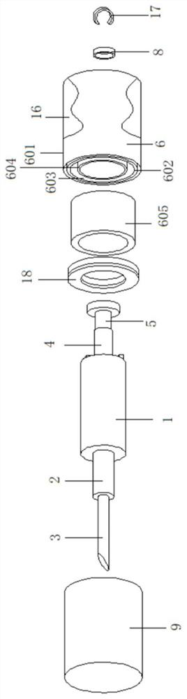
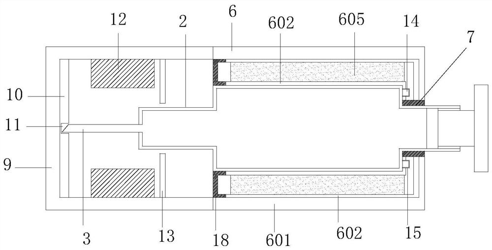
[0031] The invention provides an oncology clinical living body sampling inspection device, such as Figure 1-2 As shown, it includes a sampling tube 1 and an inspection housing 6; one end of the sampling tube 1 is connected and fixed with a needle tube 2, and the other end of the needle tube 2 is connected and fixed with a needle 3; the other end of the sampling tube 1 is connected and fixed with a suction tube 4, The suction pipe 4 is provided with a suction rod 5 inside; the suction rod 5 is closely connected with the suction pipe 4; when sampling, after the needle 3 is inserted into the patient's body, a negative pressure is formed inside the sampling pipe 1 by pulling the suction rod 5, so that Living tumor cells enter the sampling tube 1 to realize the sampling process;

[0032] The end of the sampling tube 1 is symmetrically extended outward with a block 14, and the inner wall of the inspection housing 6 is provided with a slot 15 at the position corresponding to the blo...

Embodiment 2

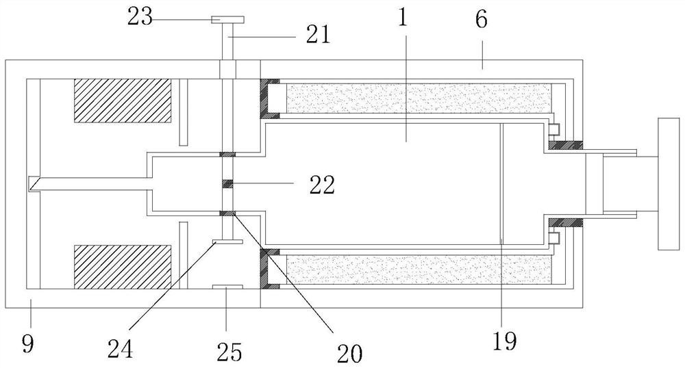
[0035] Such as image 3 As shown, the difference between this embodiment and Embodiment 1 is: a diaphragm 19, a through hole 20, an adjustment rod 21, an adjustment plate 23, a first magnetic plate 24 and a second magnetic plate 25 are added in this embodiment; the diaphragm 19 is located at The inside of the sampling tube 1 is close to one end of the suction tube 4. The diaphragm 19 can block the sampling tube 1 and the suction tube 4 to prevent the cell liquid inside the sampling tube 1 from entering the suction tube 4. The adjustment rod 21 is located in the vertical center of the needle tube 2 In the through hole 20, the size of the adjustment rod 21 matches the size of the through hole 20. The top end of the adjustment rod 21 is provided with an adjustment plate 23, and the bottom end is provided with a first magnetic plate 24. The inner wall of the inspection cover 9 corresponds to the position of the first magnetic plate 24. A second magnetic plate 25 is fixed at the ce...

Embodiment 3

[0037] Such as Figure 4-6 As shown, the difference between this embodiment and Embodiment 1 is that a temperature sensor 27, a signal converter 28 and a display screen 29 are added in this embodiment, the temperature sensor 27 is arranged on the inner wall of the inspection housing 6, and the display screen 29 is installed on the On the surface of the housing 6 for inspection, the temperature sensor 27 can detect the temperature inside the sampling tube 1, and transfer the data to the surface of the display screen 29 after being converted by the signal converter 28, so that the medical staff can check the temperature of the sampling tube 1 in real time when sending for inspection. Temperature, more convenient for medical staff to operate.

[0038] It is worth noting that the whole device is controlled by the main control button. Since the equipment matched with the control button is commonly used equipment and belongs to the existing common sense technology, its electrical co...


PUM


Abstract

The invention belongs to the technical field of medical equipment, and particularly discloses clinical living body sampling and submitting apparatus for the oncology department. The apparatus comprises a sampling pipe and a submitting shell, wherein one end of the sampling pipe is fixedly connected with a needle tube in a communication manner, the other end of the needle tube is fixedly connectedwith a needle in a communication manner, the other end of the sampling pipe is fixedly connected with an air exhaust pipe in a communication manner, a pull rod is arranged inside the air exhaust pipe,the pull rod is tightly connected with the air exhaust pipe, the submitting shell is arranged on the outer side of the sampling pipe, the submitting shell is fixedly arranged on the outer side of thesampling pipe in a sleeve manner, a pipe hole matched with the air exhaust pipe is formed in one end of the submitting shell, an O-shaped sealing ring is arranged on the inner wall of the pipe hole,and the submitting shell comprises a heat conduction ring, an ice bag groove, a heat preservation ring and a shell. According to the apparatus, through effects of the heat conduction ring made of an aluminum alloy material and the heat preservation ring made of a foam material, an ice bag in the ice bag groove can better cool the sampling pipe, and the heat preservation ring made of the foam material further has a certain damping effect and thereby can play a role in protecting the sampling pipe.

Description

technical field [0001] The invention relates to the technical field of medical equipment, in particular to an oncology clinical living body sampling and inspection device. Background technique [0002] Biopsy, also known as surgical pathological examination, refers to the technique of taking out diseased tissue from the patient's body by cutting, clamping or puncturing in response to the needs of diagnosis and treatment, and performing pathological examination; it is the most important part of diagnostic pathology. A definite histopathological diagnosis can be made for the vast majority of cases submitted for examination, which is regarded as the final clinical diagnosis. [0003] When diagnosing tumors clinically, the diagnosis is often made by puncture biopsy. At this time, a sampling and inspection device is required. A Chinese patent provides a clinical living body sampling and inspection device for oncology (Patent No.: CN202010325073.3) , through the cooperation of va...

Claims


Application Information

Patent Timeline
IPC IPC(8): A61B10/02A61B10/00A61L2/10
CPCA61B10/0096A61B10/0283A61L2/10
Inventor 尚淑平党勇
Owner 尚淑平
Why Eureka
Try Eureka