Vomit receiving device for patient of infectious department

A technology for receiving device and vomit, applied in the direction of receiving saliva, etc., can solve the problems of secondary vomiting, large air odor, etc., and achieve the effects of reducing odor, simple structure and strong practicability

Pending Publication Date: 2020-12-01
张延霞
View PDF6 Cites 2 Cited by
  • Summary
  • Abstract
  • Description
  • Claims
  • Application Information

AI Technical Summary

Problems solved by technology

[0004] The purpose of the present invention is to solve the symptom of vomiting and nausea that often occurs when patients in the Department of Gastroenterology have abdominal discomfort in the prior art. The odor is strong, and the patient will cause secondary vomiting in a heavy odor environment, and a vomit receiving device for infectious disease patients is proposed

Method used


Image

  • Vomit receiving device for patient of infectious department
  • Vomit receiving device for patient of infectious department
  • Vomit receiving device for patient of infectious department

Examples


Embodiment 1

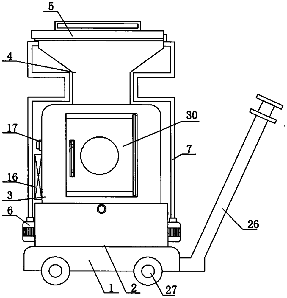
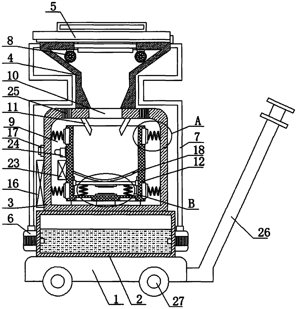
[0026] refer to Figure 1-5 , a vomit receiving device for patients in the infection department, comprising a mobile seat 1, a water tank 2 is fixedly installed on the top of the mobile seat 1, a holding seat 3 is fixedly installed on the top of the water tank 2, and a vomitus is fixedly installed on the top of the holding seat 3 The top of the vomitus receiving pipe 4 is hinged with a cover plate 5, and both sides of the water tank 2 are fixedly equipped with a water pump 6, and one end of the liquid inlet pipe of the water pump 6 extends into the water tank 2, and the outlet of the water pump 6 The liquid pipe is threadedly connected with a water pipe 7, one end of the water pipe 7 extends into the vomit receiving pipe 4 and is fixedly installed with a nozzle 8, and one side of the holding seat 3 is fixedly installed with a switch 17 and a first battery 16, and the first battery 16. The switch 17 and the water pump 6 are connected in series. The holding seat 3 is provided wi...

Embodiment 2

[0035] refer to Figure 1-5, a vomit receiving device for patients in the department of infection, comprising a mobile seat 1, the top of the mobile seat 1 is fixed with a water tank 2 by bolts, the top of the water tank 2 is fixed with a holding seat 3 by screws, and the top of the holding seat 3 The vomitus receiving pipe 4 is welded, the top of the vomitus receiving pipe 4 is hinged with a cover plate 5, the two sides of the water tank 2 are fixed with a water pump 6, and one end of the inlet pipe of the water pump 6 extends into the water tank 2 The outlet pipe of the water pump 6 is thread-tightly connected with a water pipe 7, one end of the water pipe 7 extends into the vomit receiving pipe 4 and is welded with a nozzle 8, and one side of the holding seat 3 is fixed with a switch 17 and a first battery by screws 16, and the first battery 16, the switch 17 and the water pump 6 are connected in series, the holding seat 3 is provided with a holding chamber 9, and the top i...


PUM


Abstract

The invention belongs to the technical field of gastroenterology, in particular to a vomit receiving device for a patient of infectious department. In the prior art, the abdomen of a patient in the digestive system department is uncomfortable, the symptoms of vomiting and nausea often occur, however, often a garbage can is used for receiving vomit at present, thus the peculiar smell in the air islarge, the patient is in a heavier peculiar smell environment and often secondary vomiting is caused. Aiming at the above problems, the following scheme is provided: the vomit receiving device comprises a moving seat, a water tank is fixedly mounted at the top of the moving seat, a containing seat is fixedly mounted at the top of the water tank, a vomit receiving pipe is fixedly mounted at the top of the containing seat, and a cover plate is rotatably hinged to the top of the vomit receiving pipe. The vomit collecting device is simple in structure, vomit can be diluted through water, the peculiar smell of the vomit can be reduced, meanwhile, an alarm is arranged, medical staff can be intelligently reminded to replace a garbage can in time, operation is convenient and fast, and high practicability is achieved.

Description

technical field [0001] The invention relates to the technical field of gastroenterology, in particular to a vomit receiving device for patients in the department of infection. Background technique [0002] Gastroenterology is a third-level clinical discipline that mainly studies diseases of the esophagus, stomach, small intestine, large intestine, liver, gallbladder, and pancreas. Gastroenterology has a wide variety of diseases, a wide range of medical knowledge, and complex and delicate operations. [0003] Existing gastroenterology patients often experience symptoms of vomiting and nausea when they experience abdominal discomfort. In a smelly environment, it will cause secondary vomiting, so we propose a vomit receiving device for infectious disease patients to solve the above-mentioned problems. Contents of the invention [0004] The purpose of the present invention is to solve the symptom of vomiting and nausea that often occurs when patients in the Department of Gas...

Claims


Application Information

Patent Timeline
Patent Type & Authority Applications(China)
IPC IPC(8): A61J19/04
CPCA61J19/04
Inventor 张延霞
Owner 张延霞
Why Eureka
Try Eureka