Waste container with odor control

Inactive Publication Date: 2012-09-20
HUGHES STEPHANIE +3
View PDF5 Cites 43 Cited by
  • Summary
  • Abstract
  • Description
  • Claims
  • Application Information

AI Technical Summary

Benefits of technology

[0005]The present application discloses, in various embodiments, waste containers. The waste containers comprise an enclosed waste holding receptacle and an odor control dispenser. The odor control dispenser releases

Problems solved by technology

Enclosed waste containers are frequently used to dispose of materials which emit generally continuous unpleasant and even noxious odors.
Many people have a limited means to dispose of waste, i.e. once-weekly residential garbage pickup.
Between depositions of each load, the already deposited contents tend to decay further, thus incr

Method used


Image

  • Waste container with odor control
  • Waste container with odor control
  • Waste container with odor control

Examples


first embodiment

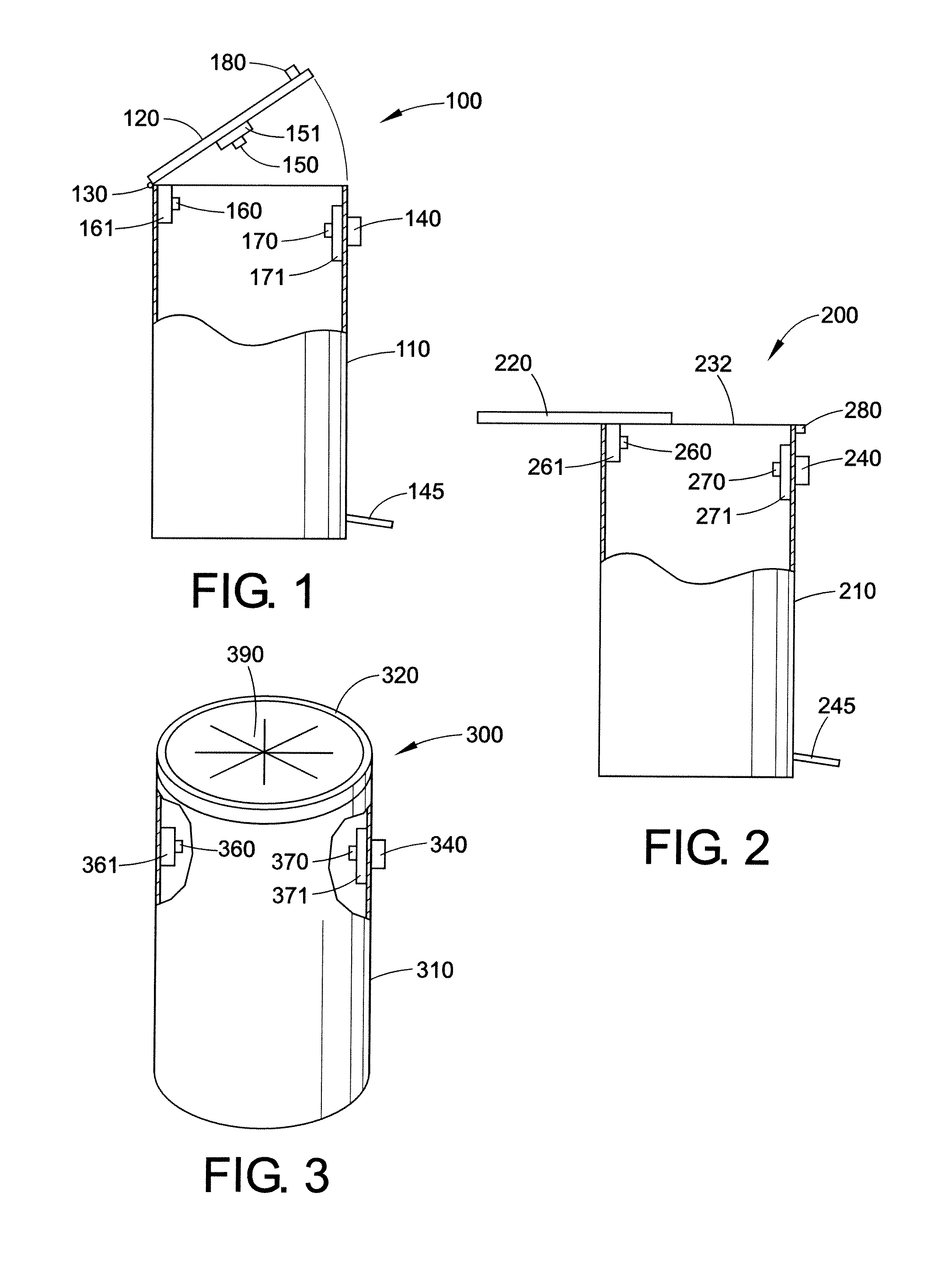
[0059]FIG. 1 shows a waste container 100 of the present disclosure. The waste container 100 comprises a vessel body 110 and a cover 120. A hinge 130 connects the cover 120 to the vessel body 110. The waste container also comprises three odor control dispensers 150, 160, and 170. Each dispenser draws an odor control composition from a different odor control reservoir 151, 161, and 171. In the depicted embodiment, the first odor control dispenser 150 is attached to the cover 120. This particular odor control dispenser 150 continuously releases the odor control composition contained in the reservoir 151. The odor control dispenser which continuously releases the odor control composition may alternatively be attached the interior of the vessel body. The second odor control dispenser 160 draws an odor control composition from reservoir 161 and is configured to release a portion of the composition into the vessel body 110 when the cover 120 is set in motion in relation to the vessel body ...

second embodiment

[0060]FIG. 2 illustrates a waste container 200 of the present disclosure. The waste container 200 comprises a vessel body 210 and a cover 220. The cover 220 slides across the vessel body 210 via a rail 232. The waste container 200 comprises an odor control dispenser 260 which draws an odor control composition from a reservoir 261 and releases a portion of the odor control composition when the cover 220 slides past a predetermined point with respect to the vessel body 210. The depicted embodiment also includes a second odor control dispenser 270 which draws odor control composition from a second reservoir 271 and releases a portion of the odor control composition when a trigger is activated, e.g. when a button 240 or a foot pedal 245 is pressed. The waste container 200 also includes a meter 280.

third embodiment

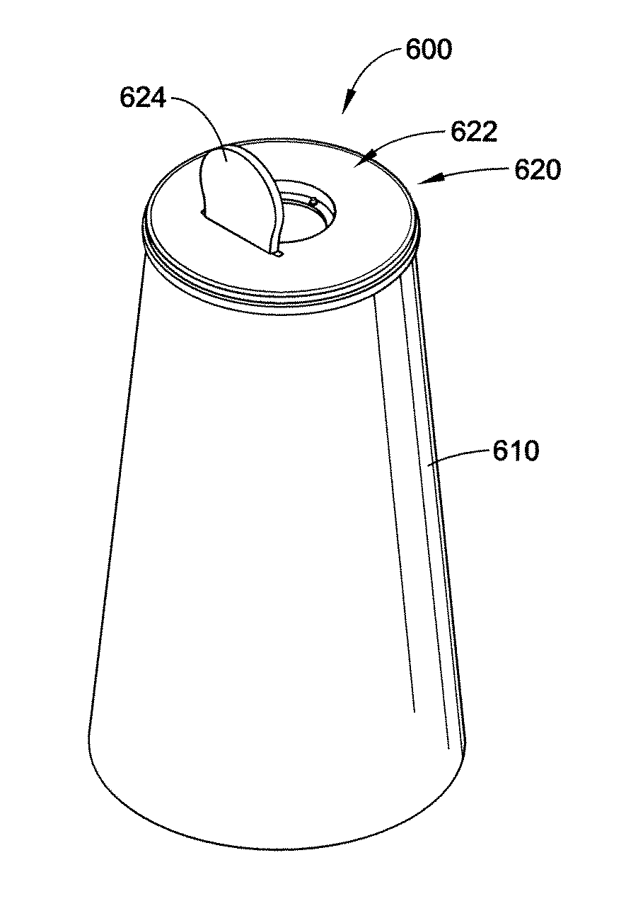
[0061]FIG. 3 depicts a waste container 300 of the present disclosure. The waste container 300 includes a vessel body 310 and a cover 320 defining a top portion of the waste container 300. The cover 320 comprises a plurality of flexible flaps 390. Waste may be placed in the vessel body 310 by pushing the waste through the flexible flaps 390 in the cover 320. After the waste material is placed into the vessel body 310, the flaps return to a closed position. The flaps 390 may be comprised of rubber or any other material which is capable of forming a seal when the flaps 390 are in a first position, i.e. when there is no pressure on the flaps 390, and forming an opening when pressure is applied to the flaps 390. The waste container 300 further comprises a first odor control dispenser 360 which draws an odor control composition from a reservoir 361 and releases a portion of the odor control composition when a waste material is being disposed of in the vessel body 310. Alternatively, the o...


PUM


Abstract

Waste containers which include a vessel body with an opening for receiving waste materials, a removable cover for operably enclosing said opening, and an odor control dispenser are disclosed. The odor control dispenser selectively dispenses an odor control agent into the vessel body when activated.

Description

BACKGROUND[0001]The present disclosure, in various embodiments, is directed to waste containers, such as pet waste receptacles, trash receptacles, diaper pails, compost containers, and medical waste containers, and the like, with odor control. The waste containers not only contain odors but also neutralize and reduce odors emitted waste materials contained therein.[0002]Enclosed waste containers are frequently used to dispose of materials which emit generally continuous unpleasant and even noxious odors. Many people have a limited means to dispose of waste, i.e. once-weekly residential garbage pickup. To reduce costs associated with garbage bags, extra garbage pickups, etc., waste containers are typically used to receive many loads of waste prior to being emptied. Between depositions of each load, the already deposited contents tend to decay further, thus increasing the foulness of the odors emitted.[0003]This problem is particularly bad for biological waste materials such as animal...

Claims


Application Information

Patent Timeline
IPC IPC(8): B65D43/16
CPCB65F1/06B65F1/1607B65F7/00B65F1/163B65F1/1646B65F1/1623
Inventor HUGHES, STEPHANIESCHNEIDER, DAVID J.SCHNEIDER, CHARLES A.HUGHES, RICHARD
Owner HUGHES STEPHANIE
Why Eureka
Try Eureka