

Solid fuel boiler and method of operating combustion apparatus
a solid fuel boiler and combustion apparatus technology, applied in the direction of lighting and heating apparatus, combustion types, fluegas recirculation, etc., can solve the problems of blown flame off, unstable flame, and insufficient reduction of fuel nox
- Summary
- Abstract
- Description
- Claims
- Application Information
AI Technical Summary
Benefits of technology
Problems solved by technology
Method used
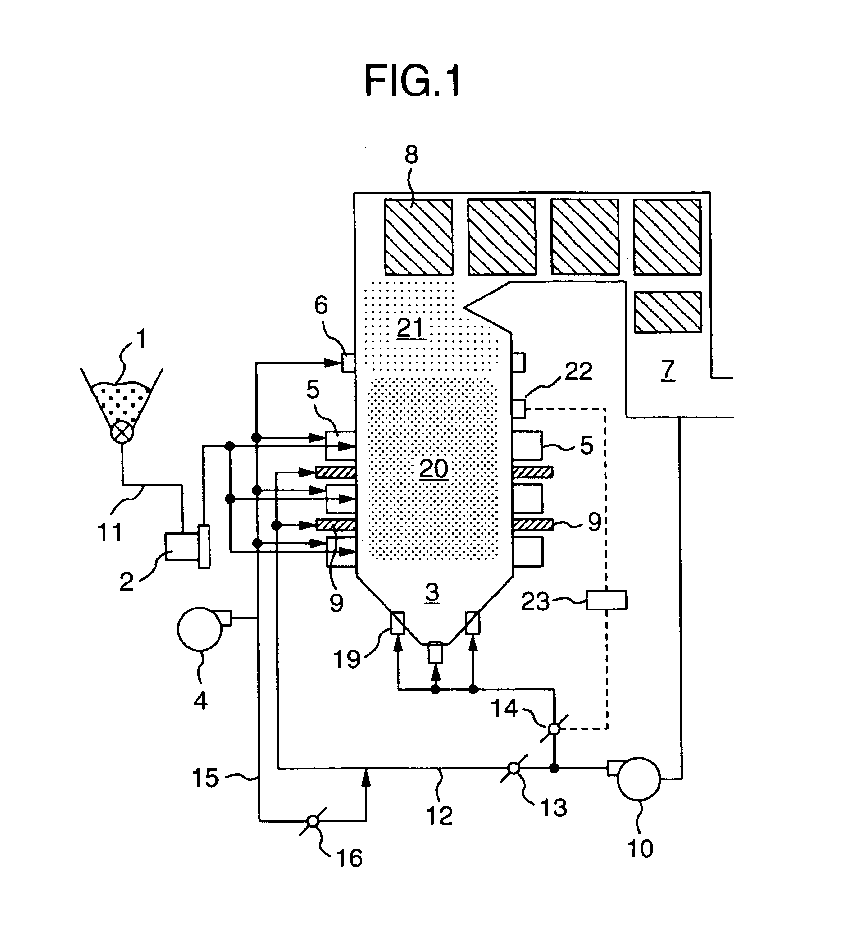
Image

Examples
first embodiment
(First Embodiment)
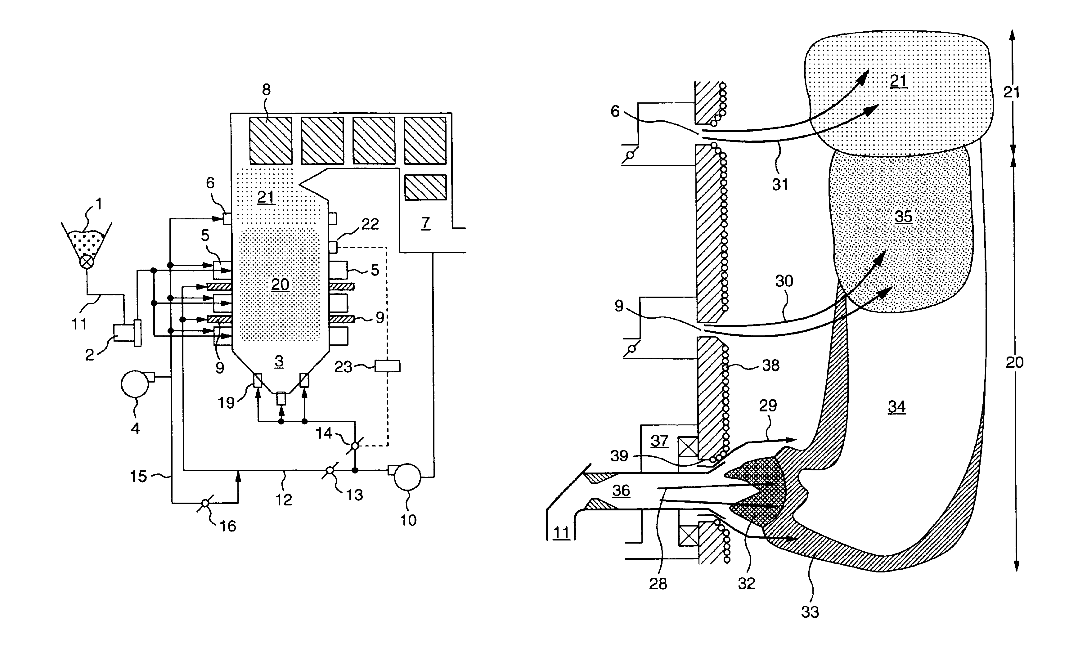
[0054]A first embodiment according to the present invention will hereinafter be described with reference to FIGS. 1 and 2. FIG. 1 is a schematic diagram of a pulverized coal boiler according to the first embodiment of the present invention. In FIG. 1, fuel passes through a fuel supply apparatus 1 and a mill 2, and is supplied to burners 5 via a fuel supply tube 11. Air for combustion from a blower 4 is branched to burners 5 and after air ports 6 and supplied into the furnace 3. At this time, the air is adjusted in predetermined flow volumes by a damper (not shown). The combustion air supplied from the burners 5 into the furnace 3 is mixed with the fuel in the vicinity of the burners 5 (in a burner zone 20) and used for lean air combustion (reducing combustion).
[0055]Furthermore, the air flows upwards in the furnace 3, unburned carbon and carbon monoxide are burned in a region 21 in which the combustion air from the after air ports 6 is mixed, and the combustion exh...
second embodiment
(Second Embodiment)
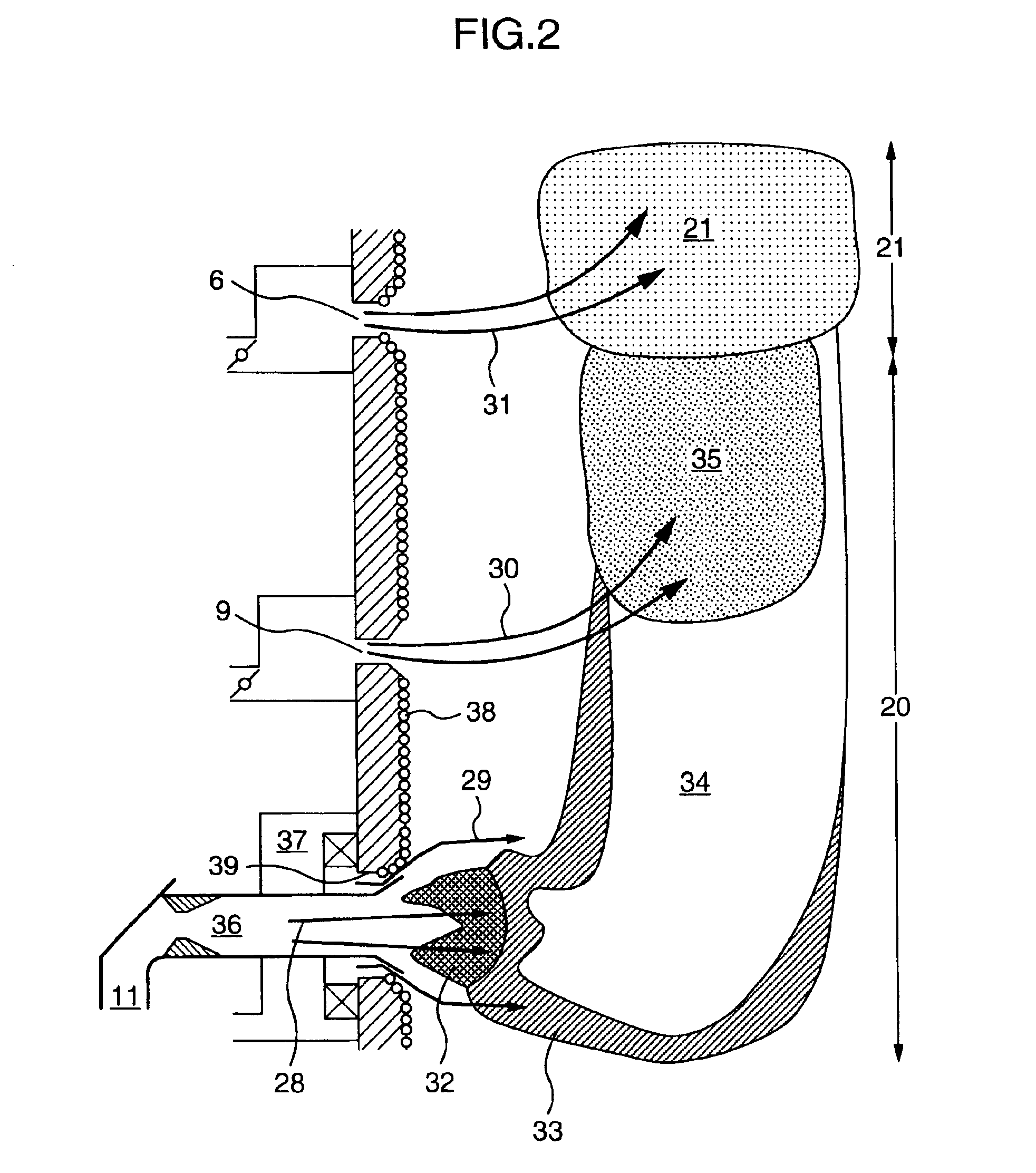
[0086]FIG. 7 shows an example in which the recirculation gas ports are disposed on the furnace wall different from the mounting surface of the burners according to the present invention. In FIG. 7, the same reference numerals as those of FIGS. 1, 4, 6 denote the same elements.
[0087]In an opposite combustion boiler in which the burners 5 are disposed on the front wall 26 and rear wall 26 of the furnace 3, the fuel spouted from the burners collides at the furnace center, and a flow toward side walls 27 may be generated. At this time, fuel particles containing the ash are apt to collide with the side walls, and therefore the ash easily sticks to the side wall middle part especially having the high thermal load.
[0088]In the embodiment shown in FIG. 7, the recirculation gas ports 9 are disposed in the vicinity of the middle of the side wall 27. Thus, the flow toward the side walls 27 from the furnace middle is moderated by the jet flow of the exhaust gas from the suppl...
PUM
 Abstract
Description
Claims
Application Information