Film cooling for the trailing edge of a steam cooled nozzle

a technology of steam cooled nozzles and trailing edges, which is applied in the direction of liquid fuel engines, machines/engines, stators, etc., can solve the problems of inability to use trailing edges for cooling, affecting and requiring costly servicing or replacement. , to achieve the effect of minimizing cooling flow, efficient film flow, and optimizing the performance of the turbine engin

Inactive Publication Date: 2006-08-08
GENERAL ELECTRIC CO
View PDF13 Cites 25 Cited by
  • Summary
  • Abstract
  • Description
  • Claims
  • Application Information

AI Technical Summary

Benefits of technology

[0007]Briefly stated, the present invention is directed to thin film cooling of the trailing edge of a nozzle for the first stage of a gas turbine engine. Cooling is affected by use of a plurality of rows of film cooling holes located adjacent the trailing edge of the nozzle, on both the concave side and convex side of the nozzle. In particular, three rows of film cooling holes are formed in the sidewalls of the nozzle on the respective concave and convex sides thereof. A first and forward row of holes extends generally longitudinally of the nozzle and comprises holes of varying sizes and angles formed at predetermined locations on the nozzle. Second and third rows of holes also extend generally longitudinally of the nozzle and also comprise holes of varying sizes and angles formed at predetermined locations on the nozzle. The second row of holes comprises a middle row of holes and the third row an aft row. Holes comprising the second row are spaced a substantial distance from those comprising the first row. However, the second and third row of holes are formed relatively close together with the holes comprising the second row being staggered in location with respect to those comprising the third row. By placing the middle and aft rows of holes closer together, and staggering the hole arrangement in these two rows, an effective film flow is achieved which cools the trailing edge of the nozzle thereby to minimize cooling flow, optimize performance of the turbine engine, reduce NOx produced by the engine, prolong the service life of the nozzle and reduce service and repair costs.

Problems solved by technology

As will be appreciated by those skilled in the art, the most extreme adverse operating conditions are generally encountered at the first stage of the turbine.
While steam adequately cools the majority of the nozzle, it is not feasible for use in cooling the trailing edge of the nozzle.
Rather, this requires a novel and advanced thin film cooling configuration in order for the trailing edge to not rapidly deteriorate once the turbine is in service which would require costly servicing or replacement of the nozzle and unacceptable down-time when the turbine is out of service.

Method used


Image

  • Film cooling for the trailing edge of a steam cooled nozzle
  • Film cooling for the trailing edge of a steam cooled nozzle
  • Film cooling for the trailing edge of a steam cooled nozzle

Examples


Embodiment Construction

[0022]The following detailed description illustrates the invention by way of example and not by way of limitation. The description clearly enables one skilled in the art to make and use the invention, describes several embodiments, adaptations, variations, alternatives, and uses of the invention, including what is presently believed to be the best mode of carrying out the invention.

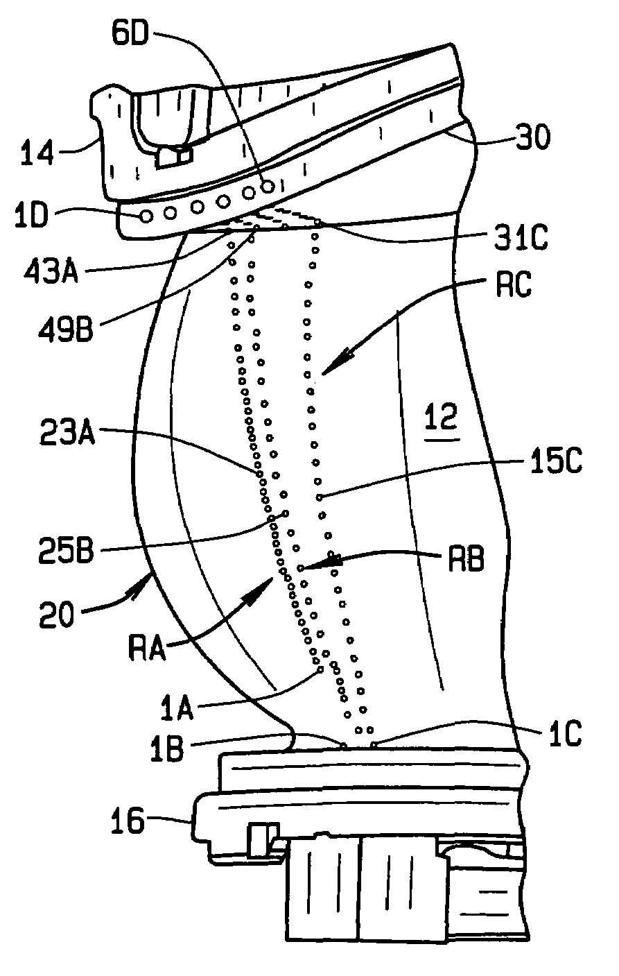
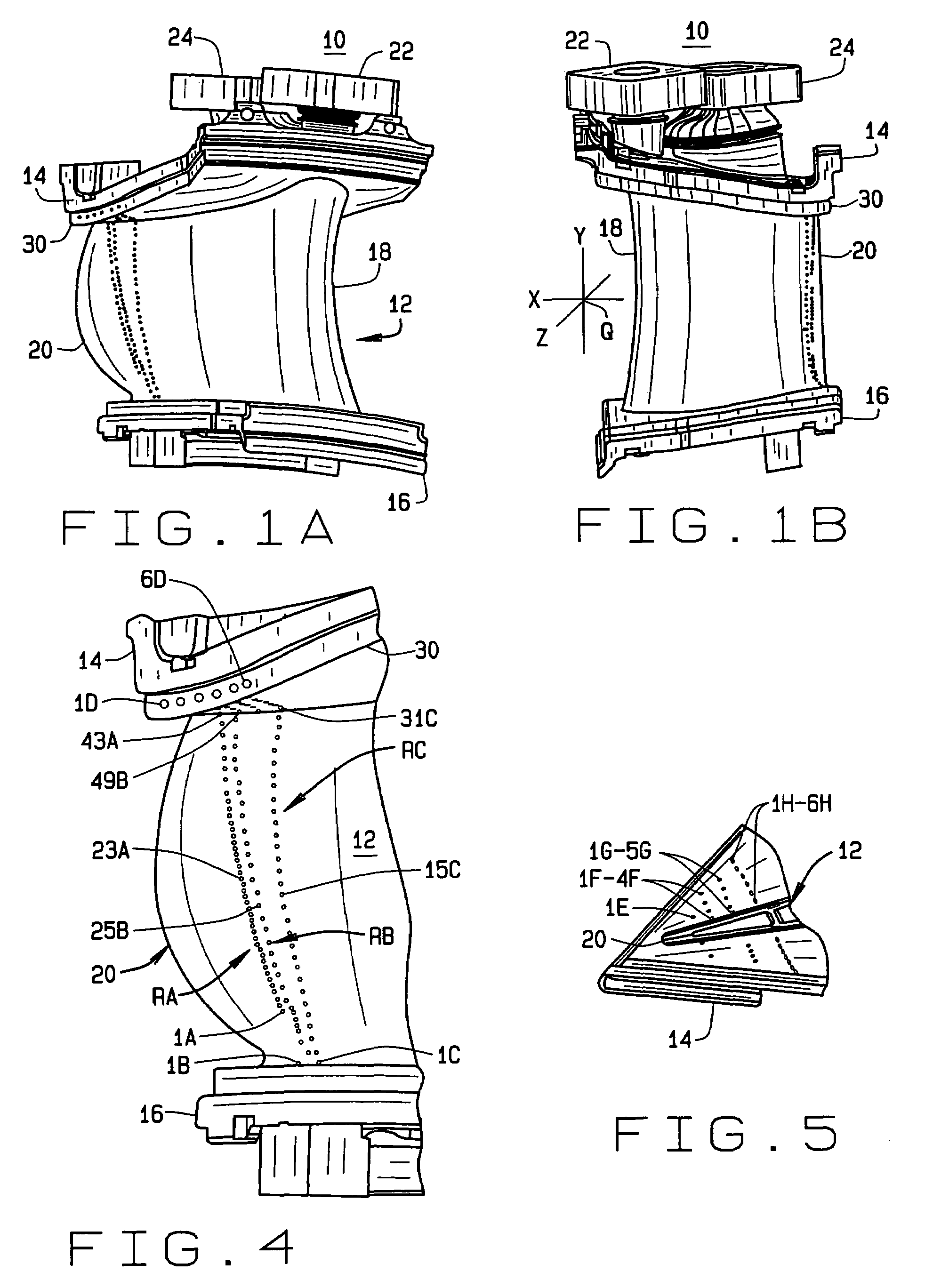
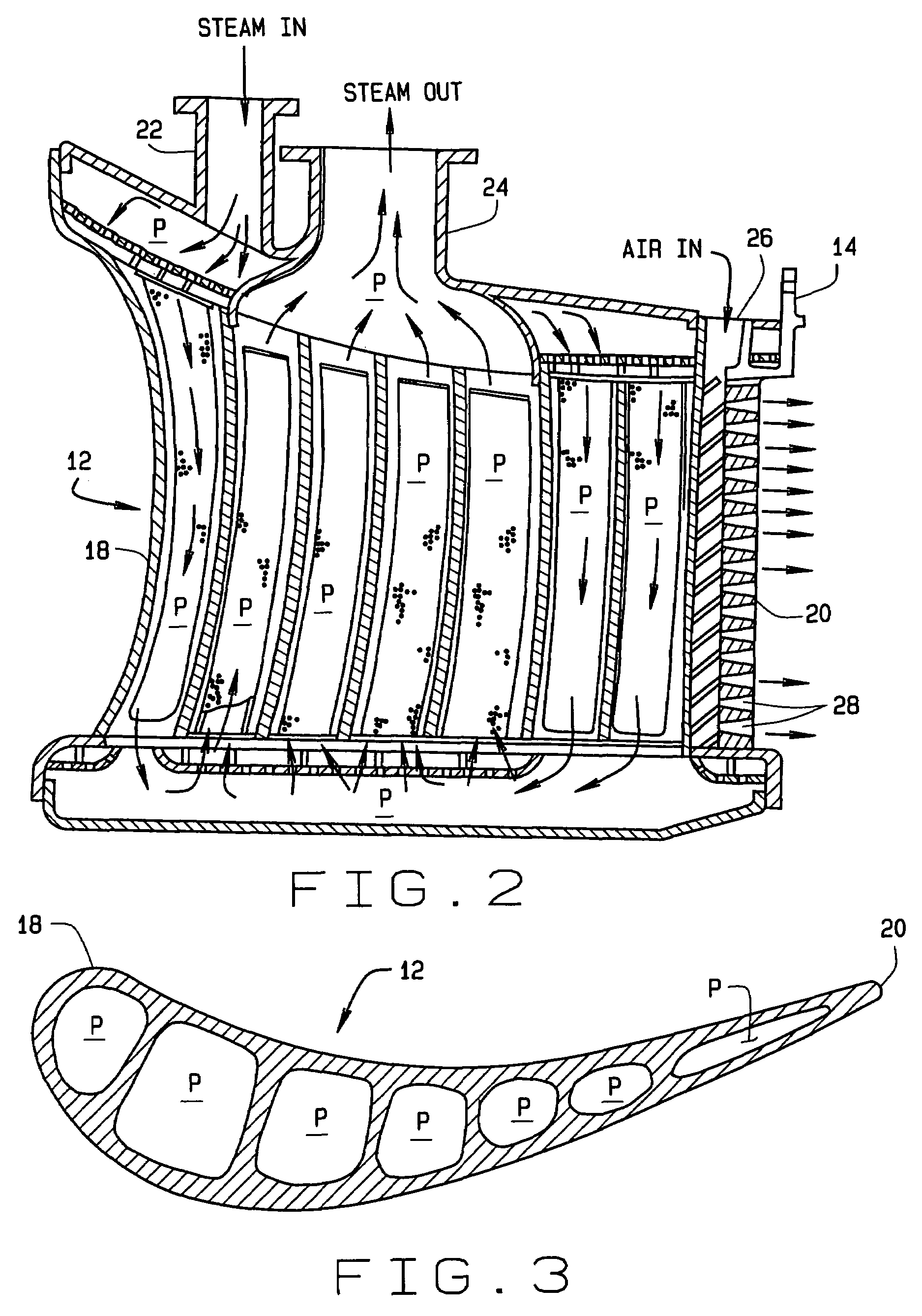
[0023]Referring to the drawings, the present invention is directed to thin film cooling for a first stage nozzle assembly, indicated generally 10 in FIGS. 1A and 1B, of a gas turbine engine. While not shown in the drawings, those skilled in the art will appreciate that nozzle assembly 10 is comprised of a plurality of circumferentially arranged vanes or airfoils indicated generally 12, the respective segments being connected to one another to form an annular array which defines a path for hot gasses passing through the first stage.

[0024]With respect to FIGS. 1A and 1B, a nozzle assembly includes an outer ...


PUM


Abstract

A nozzle assembly (10) for a turbine engine includes an inner band (16) and an outer band (14) spaced apart from each other. An airfoil (12) installed between the bands has a leading edge (18) and a trailing edge (20). The airfoil has cavities formed in it for fluid flow through the nozzle assembly. A plurality of film cooling holes (1A–6H) are formed in a sidewall of the airfoil on a concave side of the assembly, and a plurality of film cooling holes (1J–1R) are formed in a sidewall of the nozzle on a convex side thereof. The holes are formed on each side of the airfoil, adjacent the trailing edge of the nozzle, in a plurality of rows of holes including at least a forward row (C, J), an aft row (A, L), and an intermediate row (B, K). The spacing between the intermediate row and aft row is substantially closer than the spacing between the forward row and the intermediate row.

Description

CROSS-REFERENCE TO RELATED APPLICATIONS[0001]None.STATEMENT REGARDING FEDERALLY SPONSORED RESEARCH OR DEVELOPMENT[0002]Not Applicable.BACKGROUND OF THE INVENTION[0003]This invention relates to the cooling of an airfoil comprising a portion of a stator vane or nozzle of the first stage of a gas turbine engine; and more particularly, to the hole pattern formation in the airfoil for thin film cooling of a trailing edge of the airfoil.[0004]In the construction of gas turbine engines, an annular array of turbine segments is provided to form a turbine stage. Generally, the turbine stage is defined by outer and inner annular bands spaced apart from each other with a plurality of vanes or airfoils extending between the bands and circumferentially spaced from one other. This construction, in turn, defines a path for a working fluid flowing through the turbine. In a gas turbine engine, this is a hot gas. As will be appreciated by those skilled in the art, the most extreme adverse operating co...

Claims


Application Information

Patent Timeline
Patent Type & Authority Patents(United States)
IPC IPC(8): F04D29/58F01D5/18F01D9/02F01D25/12F03D11/00
CPCF01D5/186F01D9/02F01D25/12F05D2260/205F05D2240/304F05D2260/2322F05D2260/202F05D2240/122
Inventor FULLER, JASONITZEL, GARYCHIURATO, CATHYFINDLAY, MATTHEW
Owner GENERAL ELECTRIC CO
Why Eureka
Try Eureka