Oil-gas-water-sand four-phase separator

A phase separator, oil-gas-water technology, applied in filtration and separation, separation methods, chemical instruments and methods, etc., can solve problems such as nozzle blockage, affecting separation effect, time-consuming and labor-intensive, etc., and achieve the effect of easy cleaning

Active Publication Date: 2020-12-01
东营启辉石油设备有限责任公司
View PDF2 Cites 3 Cited by
  • Summary
  • Abstract
  • Description
  • Claims
  • Application Information

AI Technical Summary

Problems solved by technology

[0003] The problem in the prior art is that the three-phase separator cannot effectively remove sediment. After long-term use, impurities such as sand and stones are deposited at the bottom of the separator, and accumulation for a long time can cause nozzle blockage and affect the separation effect. In particular, the accumulation of sediment and impurities in the horizontal oil-gas-water three-phase separator used to separate sea oil is more serious
In the prior art, a sand outlet is generally connected to the bottom of the separator, and the sand falls into the sand outlet, and then the sand outlet is opened to unload the sand. However, this method can only discharge the sand impurities near the sand outlet, and there is a problem of sand cleaning. Dead corners; it is more thorough to clean up manually by entering the interior of the separator, but it needs to be shut down, and it is time-consuming and laborious

Method used


Image

  • Oil-gas-water-sand four-phase separator
  • Oil-gas-water-sand four-phase separator
  • Oil-gas-water-sand four-phase separator

Examples


Embodiment Construction

[0033] In order to enable those skilled in the art to better understand the present invention, the technical solutions of the present invention will be further described below in conjunction with the accompanying drawings.

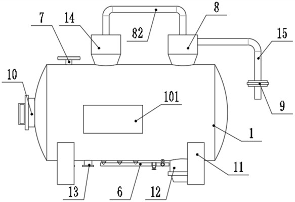
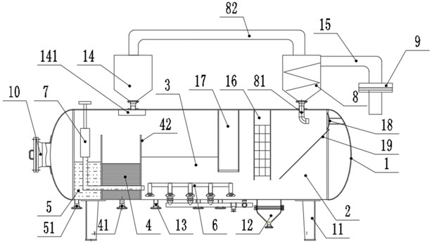
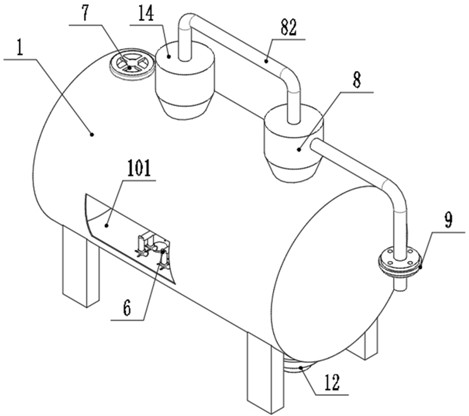
[0034]The present invention is an oil, gas, water and sand four-phase separator, comprising a tank body 1 supported by outriggers 11, the tank body 1 is made of killed steel, and after non-destructive testing, the outer wall of the tank body 1 is coated with thermal insulation coating Floor. The tank body 1 is a cylinder structure with two ends as arc surfaces, and one end is provided with a manhole 10, which is convenient for manual internal maintenance and cleaning. The top of the front end of the tank body 1 is connected with a swirl tube 8, the inner wall of the swirl tube 8 is connected with a spiral plate, and the spiral plate forms a spiral channel, and the swirl tube 8 is connected with a liquid inlet pipe 15, which enters the swirl tube through th...


PUM


Abstract

The invention discloses an oil-gas-water-sand four-phase separator. The separator comprises a tank body, a rotational flow cylinder is connected to the top of the front end of the tank body, a liquidinlet pipe is connected to the rotational flow cylinder, and the lower end of the rotational flow cylinder communicates with the interior of the tank body through a rotational flow lower pipe; the topof the tank body is also connected with a gas phase outlet; a corrugated plate group, an oil weir plate, an oil chamber and a water chamber which are connected to the inner wall of the tank body aresequentially arranged in the tank body from front to back; the lower end of the oil chamber is connected with an oil discharging pipe, the lower end of the water chamber is connected with a water discharging pipe, the front side face of the tank body is connected with a baffling bent plate, the lower end opening of a rotational flow lower pipe faces the baffling bent plate, an inclined down-flow plate is arranged below the baffling bent plate, and the two sides of the down-flow plate are connected to the inner side face of the tank body; a sand storage barrel connected to the bottom of the tank body is arranged below the down-flow plate, and an opening and closing valve is arranged at the lower end of the sand storage barrel; and the bottom of the tank body is connected with a sediment cleaning assembly capable of automatically cleaning sediment on the bottom surface of the tank body. The separator not only can realize effective separation of oil, gas and water, but also can realize on-line and off-line sand cleaning, and the cleaning is more thorough.

Description

technical field [0001] The invention relates to the technical field of petroleum multiphase separation devices, in particular to an oil, gas, water and sand four-phase separator. Background technique [0002] In oil and gas field surface engineering, oil well production fluid is mostly a mixed liquid composed of oil, gas, water, sand, etc., and the mixed liquid migrates in the formation pores and wellbore, inevitably carrying solid impurities such as sediment. The three-phase separator is an indispensable equipment for the separation of oil, gas and water. When the three-phase separator is working, the mixture of oil, gas and water enters the degassing chamber, and a large amount of crude oil associated gas is removed by cyclone separation and gravity. Then the degassed oil-water mixture enters the pretreatment chamber, where it settles initially, and is consolidated and rectified by the corrugated plate group to pierce the foam caused by the tumbling of oil and water, and t...

Claims


Application Information

Patent Timeline
Patent Type & Authority Applications(China)
IPC IPC(8): B01D36/00
CPCB01D36/001B01D36/003
Inventor 门冬亮郭德宽
Owner 东营启辉石油设备有限责任公司
Why Eureka
Try Eureka