
Cutting equipment for aluminum veneer and cutting process thereof

A technology of cutting equipment and aluminum veneer, which is applied in the direction of milling machine equipment, milling machine equipment details, metal processing equipment, etc., can solve the problems of low cutting efficiency, unstable operation, and uneven lines of the cutting end surface, and achieve high cutting size accuracy, Improved cutting efficiency and beautiful end face appearance

Inactive Publication Date: 2020-12-01
江苏佰大幕墙科技有限公司
View PDF8 Cites 0 Cited by
  • Summary
  • Abstract
  • Description
  • Claims
  • Application Information

AI Technical Summary

Problems solved by technology

[0002] At present, due to the processing of hyperbolic aluminum veneers, the blanking generally enlarges the surrounding dimensions, and after the hyperboloid is formed, the excess dimensions around the surroundings are cut off; while the end lines around the hyperbolic aluminum veneers are generally irregular curved lines (or Free curve); therefore, the existing processing technology of the end face of the hyperbolic aluminum veneer is generally cut by hand with a curve saw, and then the size of the chord length around it is measured; however, this method has high manual requirements for the operator, unstable operation, and low cutting efficiency. The cutting end surface is not smooth, not smooth, there are burrs, the dimensional accuracy is not high, and the appearance of the end surface is not beautiful.

Method used


Image

  • Cutting equipment for aluminum veneer and cutting process thereof
  • Cutting equipment for aluminum veneer and cutting process thereof
  • Cutting equipment for aluminum veneer and cutting process thereof

Examples


Embodiment Construction

[0031] The technical solutions of the present invention will be clearly and completely described below through specific embodiments.

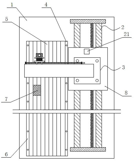
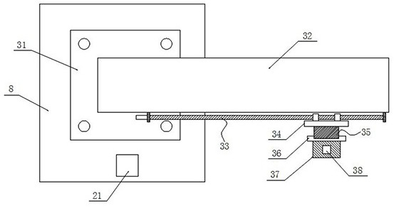
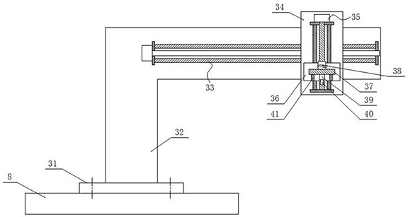
[0032] A kind of cutting equipment for aluminum veneer and its cutting process of the present invention, comprising machine tool 1, first moving mechanism 2, cutting device 3, first bottom plate 8, first limiting plate 4, second limiting plate 6, Positioning plate 5 and tire frame 7; Concrete structure such as Figure 1~7 As shown, the machine tool 1 is arranged horizontally, and the second limiting plate 6 and the first limiting plate 4 are arranged horizontally and sequentially on the left half of its upper surface from left to right. The second limiting plate 6 and the first limiting plate Limiting plates 4 are arranged horizontally and vertically, and a positioning plate 5 for positioning is also installed horizontally between the two. The positioning plate 5 is surrounded by the second limiting plate 6 and the first limiting plate 4. The ...


PUM


Abstract

The invention discloses cutting equipment for an aluminum veneer and a cutting process thereof. The cutting equipment comprises a machine tool, a first moving mechanism, a cutting device, a first bottom plate, a first limiting plate, a second limiting plate, a positioning plate and a jig frame; the second limiting plate and the first limiting plate are horizontally and longitudinally arranged on the left half portion of the machine tool, a positioning plate is arranged between the second limiting plate and the first limiting plate, the positioning plate is matched with a square area defined bythe second limiting plate and the first limiting plate, and the jig frame is arranged on the positioning plate; the first moving mechanism is horizontally and longitudinally arranged at the right half part of the machine tool, and the first bottom plate is horizontally arranged on the first moving mechanism and is in sliding connection with the first moving mechanism; and the cutting device is arranged on the first bottom plate, and the cutting end of the cutting device is arranged vertically downwards and moves horizontal-transversely, horizontal-longitudinally and vertically up and down inthe square area. According to the cutting equipment, by arranging the first moving mechanism, the second moving mechanism and a third moving mechanism, three-dimensional cutting in the horizontal transverse direction, the horizontal longitudinal direction and the vertical direction is achieved, and the cutting efficiency is improved.

Description

technical field [0001] The invention relates to the technical field of cutting aluminum veneers, in particular to cutting equipment and a cutting process for aluminum veneers. Background technique [0002] At present, due to the processing of hyperbolic aluminum veneers, the blanking generally enlarges the surrounding dimensions, and after the hyperboloid is formed, the excess dimensions around the surroundings are cut off; while the end lines around the hyperbolic aluminum veneers are generally irregular curved lines (or Free curve); therefore, the existing processing technology of the end face of the hyperbolic aluminum veneer is generally cut by hand with a curve saw, and then the size of the chord length around it is measured; however, this method has high manual requirements for the operator, unstable operation, and low cutting efficiency. The cutting end surface has defects such as uneven and unsmooth lines, burrs, low dimensional accuracy, and unsightly appearance of ...

Claims


Application Information

Patent Timeline
IPC IPC(8): B23C3/00B23Q3/00
CPCB23C3/00B23Q3/00
Inventor 马涛杨强
Owner 江苏佰大幕墙科技有限公司
Learn More