
Harmonic reducer tooth surface machining method and device

A harmonic reducer and processing device technology, applied in the field of harmonic reducer, can solve the problems of machine tools relying on imports, small current, and low production efficiency

Pending Publication Date: 2020-12-01
查世梁
View PDF0 Cites 2 Cited by
  • Summary
  • Abstract
  • Description
  • Claims
  • Application Information

AI Technical Summary

Problems solved by technology

The current allowed to pass through the thin metal wire is small, not only the production efficiency is proportional to the current size, but also the tooth surface after wire cutting needs to be ground, the tooth shape is similar, and the machine tool depends on imports

Method used


Image

  • Harmonic reducer tooth surface machining method and device
  • Harmonic reducer tooth surface machining method and device
  • Harmonic reducer tooth surface machining method and device

Examples


Embodiment 1

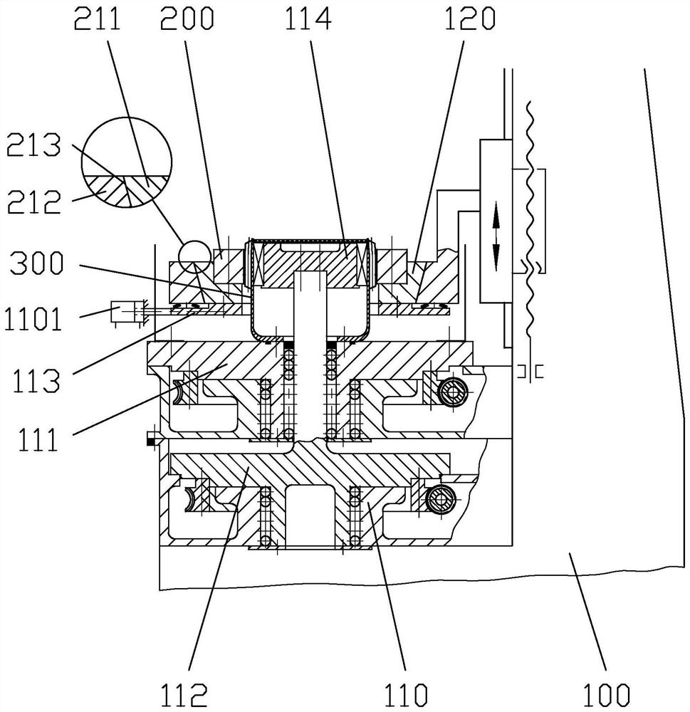
[0048] Embodiment 1, with reference to figure 1 , there are two closed-loop CNC turntables (turntable part 110) with a rotation accuracy of 1.0" on the bed and a rigid wheel fixture part (movable fixture part 120) that can move up and down, that is, the rigid wheel fixture 210 is located on the movable fixture part 120 , the movable fixture part 120 is used to fix the rigid wheel 200 to be processed, and the turntable part 110 includes a flexspline turntable 111 and a wave generator turntable 112. There is a flexible bearing and a wave generator 114, the rotation axes of the flexspline turntable and the wave generator turntable coincide, and the flexspline turntable 111 is provided with a flexspline clamp for fixing the flexspline 300, and the wave generator A wave generator fixture is provided on the turntable 112 . The rotation axes of the flexspline turntable 111 and the wave generator turntable 112 overlap, the flexspline fixture 113 is provided on the flexspline turntabl...

Embodiment 2

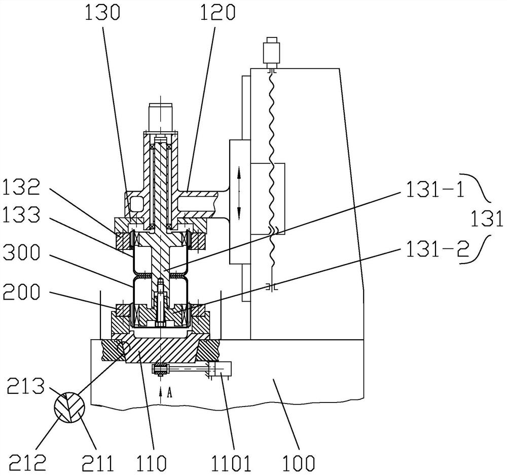
[0054] Embodiment 2, with reference to image 3 , the turntable part 110 is used to fix the steel wheel 200 to be processed, that is, the steel wheel fixture 210 is located on the turntable part 110, and the mother harmonic reducer 133 is arranged on the movable fixture arm, and the mother harmonic reducer 133 includes a mother harmonic reducer The wave generator 131, the rigid wheel 132 of the mother harmonic reducer, the flexible wheel 133 of the mother harmonic reducer, and the flexible wheel 300 as a tool is arranged on the flexible wheel 133 of the mother harmonic reducer. The flexspline 133 of the female harmonic reducer is provided with a female wave generator, a female flexible bearing and a flexspline 300 as a female cutter. The flexspline 300 as a tool is provided with a flexible bearing and a wave generator, wherein the wave generator 131 of the mother harmonic reducer simultaneously drives the flexspline 133 of the mother harmonic reducer and the tool flexspline 30...


PUM


Abstract

The invention discloses a harmonic reducer tooth surface machining method. A rigid wheel is machined through a conjugate tooth profile electric spark generating method. The machined rigid wheel is connected with a positive electrode of an electric spark power supply; and a flexible gear is connected with a negative electrode of the electric spark power supply, a flexible bearing and a wave generator are arranged in the flexible gear, the transmission ratio among the flexible gear, the rigid gear and the wave generator is controlled through a transmission chain or a harmonic reducer of a machining device, and the tooth portion of the flexible gear comprises a conical tooth section, a finish machining section and a running-in section. The conjugate tooth profile electric spark generating method is adopted for machining, the transmission ratio among the flexible gear, the rigid gear and the wave generator is consistent with the design of a harmonic reducer, the obtained tooth profile of the rigid gear is a no-load conjugate tooth profile conforming to the effect of no theoretical error, and the conjugate tooth profile under the load condition is obtained through loading running-in.

Description

technical field [0001] The invention relates to the technical field of harmonic reducers, in particular to a method for processing tooth surfaces of harmonic reducers and a processing device thereof. Background technique [0002] The structure of the harmonic reducer mainly includes a wave generator, a flexible bearing, a flexible wheel, and a rigid wheel. Among them, the flexible spline is a flexible external gear, and the rigid spline is a rigid internal gear. The harmonic reducer has the advantages of compact structure, small size, light weight, large transmission ratio and carrying capacity, and high transmission precision. The motion or power is usually input by the wave generator, the rigid spline is stationary, and the motion is output by the flexible spline; or the flexible spline is stationary, and the motion is output by the rigid spline. [0003] When the harmonic reducer without any error is working, the flex spline is deformed at a uniform speed by the action ...

Claims


Application Information

Patent Timeline
Patent Type & Authority Applications(China)
IPC IPC(8): B23H9/00
CPCB23H9/003
Inventor 查谦查世樑查理邓谦
Owner 查世梁
Learn More