

Anti-vibration device and method for machining diesel engine base rack
An anti-vibration device, diesel engine technology, applied in metal processing equipment, metal processing mechanical parts, manufacturing tools, etc., can solve the problems of insufficient support, difficult to ensure the roughness of the processing surface, small contact surface, etc., to improve the processing roughness and Flatness, improved anti-vibration effect, and large support contact area
- Summary
- Abstract
- Description
- Claims
- Application Information
AI Technical Summary
Problems solved by technology
Method used
Image

Examples
Embodiment 1
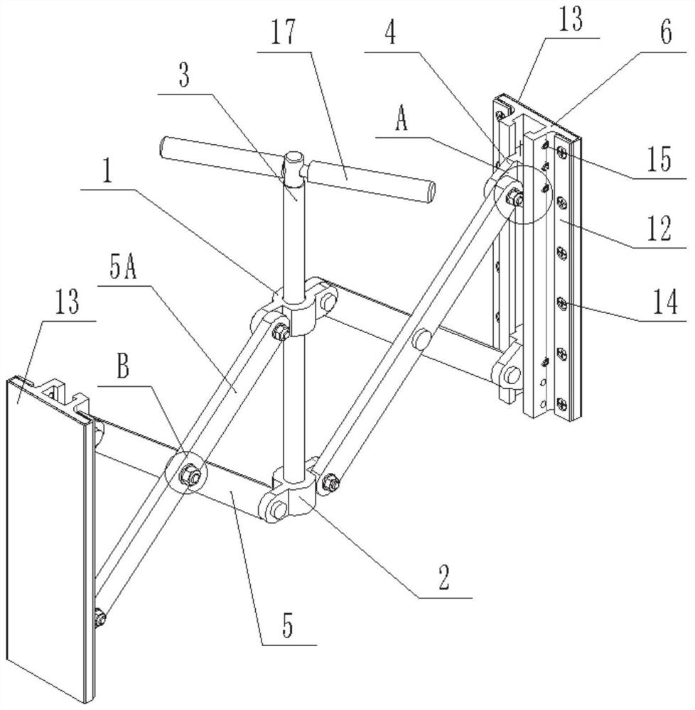
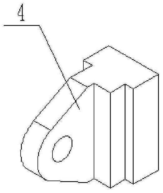
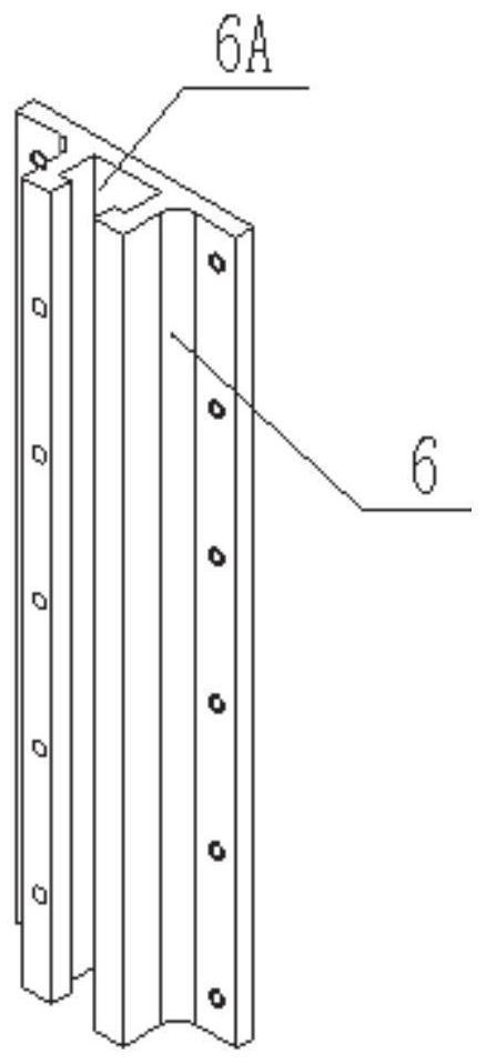
[0037] Such as Figure 1-Figure 2 As shown, an anti-vibration device for machining a diesel engine frame is provided, which includes two pressure plates 6 arranged side by side. A scissor bracket is connected between them, and the scissor bracket can adjust and fix the distance between the two pressure plates 6 through scissor deformation under the condition that the two pressure plates 6 are parallel.
[0038] In this implementation, in order to avoid damage to the surface of the plate to be damped due to rigid contact between the surface of the pressure plate and the plate to be damped, and to avoid excessive local pressure caused by poor contact between the pressure plate and the plate to be damped In a large case, the outer surface of the pressure plate (that is, in contact with the plate to be damped) is covered with a rubber pad, and the two ends of the rubber pad bypass the outer surface of the pressure plate and then extend into the opposite sides of the two pressure p...
Embodiment 2
[0050] This embodiment provides an anti-vibration method for processing a diesel engine frame, which uses the above-mentioned anti-vibration device for processing a diesel engine frame, and includes the following steps:
[0051] Before processing the damping plate 1801, adjust the distance between the two pressing plates 6 to the minimum state;
[0052] Place the two pressure plates 6 in the cavity between the two plates to be damped;
[0053] The distance between the two pressing plates 6 is increased by the deformation of the scissor bracket, so that the two pressing plates 6 are respectively tightly pressed against the surface of the plate to be damped on both sides.
[0054] Further, when the plates 1801 to be damped are arranged in a row in the frame 18 of the diesel engine, the inner chambers between adjacent plates are respectively provided with one anti-vibration device for the processing of the frame of the diesel engine, so that the shock absorbers to be damped The ...
PUM
 Abstract
Description
Claims
Application Information