Blade hoisting tool and hydraulic system thereof

A hydraulic system and hoisting technology, applied in the safety of fluid pressure actuation system, fluid pressure actuation system components, transportation and packaging, etc., can solve the problems of low operation efficiency, poor safety, affecting the normal operation of the unit, etc., and improve the installation Efficiency and safety

Active Publication Date: 2020-12-01
JIANGSU GOLDWIND SCI & TECH CO LTD +1
View PDF4 Cites 2 Cited by
  • Summary
  • Abstract
  • Description
  • Claims
  • Application Information

AI Technical Summary

Problems solved by technology

[0002] At present, the blade length of the offshore unit has exceeded 90 meters, and the weight exceeds 35 tons. The traditional horizontal single-blade fixture requires a barring structure. The load is getting bigger and bigger, which leads to the deformation of the generator cover structure (connection position with the cranking) during the cranking process, which affects the normal operation of the unit, and because the blade length is too long, the three-blade installation is limited by the installation ship , there is a great risk of blade turning over
[0003] The hydraulic system of the existing blade hoisting tooling cannot guarantee the safety of the blade hoisting process, and cannot effectively control the blade rotation. When the blade rotates in the air, the fretting performance is poor and the impact is large.
In addition, the hydraulic system of the existing blade hoisting tooling is poor in safety, including poor reliability and low operating efficiency of the blade hoisting tooling of the hydraulic system

Method used


Image

  • Blade hoisting tool and hydraulic system thereof
  • Blade hoisting tool and hydraulic system thereof
  • Blade hoisting tool and hydraulic system thereof

Examples


Embodiment Construction

[0030] The hydraulic system according to the embodiment of the present application can drive at least two oil cylinders to expand and contract asynchronously, and can be adapted to drive the pitching and rotating mechanism of the blade hoisting tool, so as to adjust the attitude of the blade during hoisting, such as the tilt angle or pitch angle.

[0031] Embodiments of the present application will be described below with reference to the drawings in which like reference numerals designate like parts throughout.

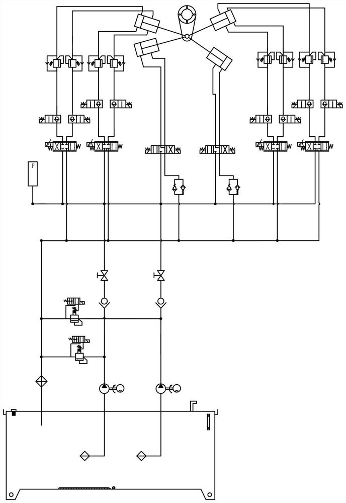
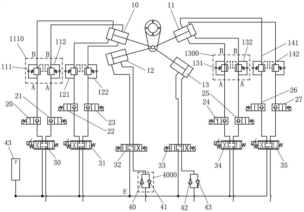
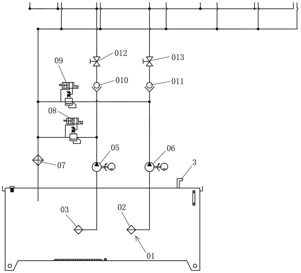
[0032] Figure 1 to Figure 3 is a schematic diagram of a hydraulic system according to an embodiment of the present application.

[0033] A hydraulic system according to an embodiment of the present application may include driving units 05 and 06 , a first pressure maintaining unit 1110 , a second pressure maintaining unit 1300 , a first valve unit 30 and a second valve unit 34 .

[0034] The drive units 05 and 06 can be the power elements of the hydraulic system, an...


PUM


Abstract

The invention provides a blade hoisting tool and a hydraulic system thereof. The hydraulic system includes a driving unit, a first pressure maintaining unit, a second pressure maintaining unit, a first valve unit and a second valve unit; the driving unit drives hydraulic oil in a hydraulic system to form oil supply paths and oil return paths and supplies oil to oil cylinders through an oil supplypath or releasing the hydraulic oil of the oil cylinders through an oil return path, and the oil cylinders include a first oil cylinder with a first small cavity and a first large cavity and a secondoil cylinder with a second small cavity and a second large cavity; the first pressure maintaining unit is connected between the first oil cylinder and the driving unit so as to enable the first oil cylinder to supply and return the oil; the second pressure maintaining unit is connected between the second oil cylinder and the driving unit so as to enable the second oil cylinder to supply and returnthe oil; the first valve unit is arranged on a common path of the oil supply path and the oil return path of the first oil cylinder, and the second valve unit is arranged on a common path of the oilsupply path and the oil return path of the second oil cylinder; and the first oil cylinder and the second oil cylinder stretch out and draw back asynchronously to drive a pitching rotating mechanism to rotate, so that blades can perform pitching rotation.

Description

technical field [0001] The invention relates to the technical field of wind power generation, in particular to a blade hoisting tool and a hydraulic system thereof. Background technique [0002] At present, the blade length of the offshore unit has exceeded 90 meters, and the weight exceeds 35 tons. The traditional horizontal single-blade fixture requires a barring structure. The load is getting bigger and bigger, which leads to the deformation of the generator cover structure (connection position with the cranking) during the cranking process, which affects the normal operation of the unit, and because the blade length is too long, the three-blade installation is limited by the installation ship , There is a great risk of blade turning over. [0003] The hydraulic system of the existing blade hoisting tooling cannot guarantee the safety of the blade hoisting process, and cannot effectively control the blade rotation. When the blade rotates in the air to start and stop, the...

Claims


Application Information

Patent Timeline
Patent Type & Authority Applications(China)
IPC IPC(8): B66C1/44B66C13/08B66C13/18F15B11/16F15B13/06F15B15/14F15B20/00F15B21/041
CPCB66C1/447B66C13/08B66C13/18F15B11/16F15B13/06F15B15/149F15B20/00F15B21/041F15B2211/71F15B2211/865B66C2700/00
Inventor 章钟伟方晶程伟黄可唯黄建伟朱钰
Owner JIANGSU GOLDWIND SCI & TECH CO LTD
Why Eureka
Try Eureka