Follow-up support system for building jacking construction

A technology for supporting systems and buildings, applied in construction, bridge construction, erection/assembly of bridges, etc., can solve the problems of difficult installation, high risk, poor flatness of the superstructure, etc., and achieve easy installation and use, high safety and reliability. , the effect of good safety and reliability

Active Publication Date: 2014-11-05
SHANGHAI URBAN CONSTRUCTION MUNICIPAL ENGINEERING (GROUP) CO LTD
View PDF8 Cites 0 Cited by
  • Summary
  • Abstract
  • Description
  • Claims
  • Application Information

AI Technical Summary

Problems solved by technology

[0005] 1. In this method (system), a micrometer is used to measure the distance between the supporting device and the superstructure to control the lifting of the supporting device. This design concept is difficult to realize in actual construction
Different from the field of machining technology, in the field of building construction technology, it is generally impossible to achieve high precision, and the flatness of the bottom of the upper structure is relatively poor. In this environment, there will be large errors in the use of micrometers
[0006] 2. Even if the above-mentioned error factors are put aside, the above-mentioned follow-up support system still has problems that cannot be overcome
However, when the jacking hydraulic cylinder loses pressure and falls back, the load changes instantaneously. At this time, the upper structure will fall almost without support, which is very dangerous during construction.
[0007] 3. The servo motor mounted on the following support device is relatively large, which makes the plane size of the follow support device large and difficult to install during use
[0008] From the above discussion, it can be seen that the automatic following support system and method have certain insurmountable defects in actual use, and there are still relatively large risks when applied to bridge jacking construction.

Method used


Image

  • Follow-up support system for building jacking construction
  • Follow-up support system for building jacking construction
  • Follow-up support system for building jacking construction

Examples


Embodiment 1

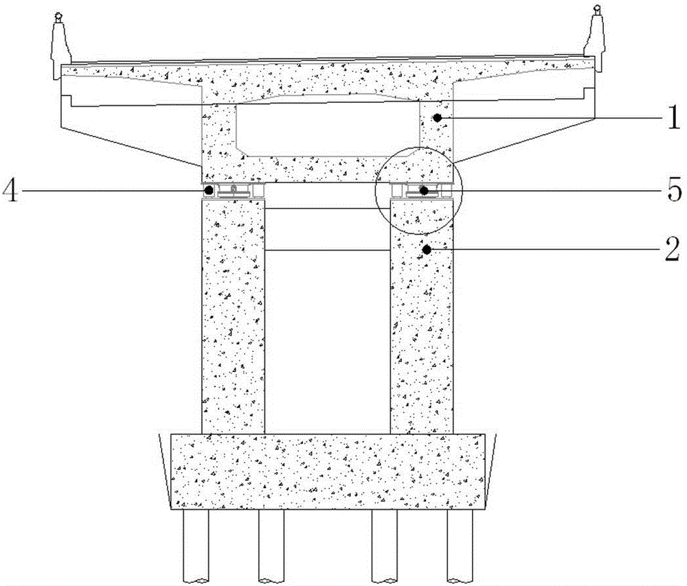
[0033] see Figure 1-3 As shown, the superstructure of the bridge involved in this embodiment adopts a three-span variable cross-section prestressed concrete continuous box girder 1 , and the bottom of the continuous box girder 1 is supported by pier 2 . see figure 1 , The pier 2 in this embodiment includes two main piers and two side piers. Based on this structure, this embodiment adopts the direct jacking method, that is, the pier 2 (main pier and side pier) is used as the counter force basis, and the jacking hydraulic cylinder 4 is installed between the pier 2 and the bottom of the continuous box girder 1, through the PLC computer Synchronous control, the method of jacking up the box girder as a whole (the upper part of the box girder needs to be reinforced) achieves the purpose of raising the deck level of the main bridge.

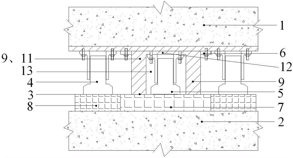
[0034] The follow-up support system mainly includes a follow-up housing 9 and a follow-up hydraulic cylinder 5 . in:

[0035] The following housin...

Embodiment 2

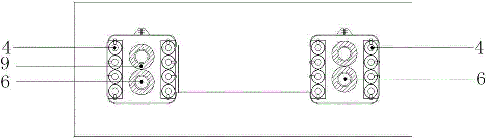
[0048] see Figure 4-5 In this embodiment 2, a number of reinforcing ribs 10 are arranged in the following housing 9, and the reinforcing ribs 10 are vertically welded on the installation bottom plate 12, and the end faces on both sides are welded to the inner surface of the side plate 11 or welded to each other, and The following housing 9 is divided into several cavities 13 . In each cavity 13, a following hydraulic cylinder 5 is set and fixed. The lower end faces of the reinforcing ribs 10 are flush with the lower end faces of the side plates 11 and combined constitute a supporting surface following the housing. In Embodiment 2, the way that the following hydraulic cylinder 5 is installed on the following housing 9 and that the following housing 9 is installed on the bottom of the box girder 1 is the same as that of Embodiment 1, so it will not be repeated here.

[0049] Due to the need to support the upper structure, the following hydraulic cylinders 5 are usually used i...

Embodiment 3

[0051] see Figure 6 , In the present embodiment 3, the following housing 9 is roughly in the shape of a cuboid steel square tube, which is composed of four side plates 11 welded to each other. The outer edge of one end of the side plate 11 is welded with a flange 6 for bolting to the box girder 1, and the other end constitutes a supporting surface. The height of the side plate 11 is also the same as the minimum height of the jacking hydraulic cylinder 4 . The hollow inner cavity of the following housing 9 is used for fitting the following hydraulic cylinder 5 .

[0052] During installation, the following housing 9 and the following hydraulic cylinder 5 are respectively fixed to the box girder 1. First, the base of the following hydraulic cylinder 5 is bolted to the bottom of the box beam 1, and then the following housing 9 is set outside the following hydraulic cylinder 5. , and the flange 6 and the box girder 1 are bolted and fixed by bolts.


PUM


Abstract

The invention relates to bridge heightening technology, in particular to a follow-up support system for building jacking construction, which comprises a follow-up casing and a follow-up hydraulic cylinder. The follow-up casing is provided with an upper support surface and a lower support surface parallel to each other and is provided with at least one cavity perpendicular to the upper support surface and the lower support surface. Each cavity is provided with an opening on the lower support surface. The follow-up hydraulic cylinder is sleeved into the cavity. The follow-up casing and the follow-up hydraulic cylinder are respectively fixed at the bottom of a superstructure, or fixedly connected with each other prior to being integrally installed at the bottom of the superstructure, and the upper support surface is attached with the bottom of the superstructure. The follow-up support system is high in safety and reliability, good in synchronousness, high in operability and high in overall stress performance and reliability guarantees bridge jacking safety.

Description

technical field [0001] The invention relates to bridge heightening technology, in particular to a follow-up support system for building jacking construction. Background technique [0002] At present, in the reconstruction of rivers, railways and highways, the clearance of bridges and the connection between the alignment of existing bridges and the alignment of new bridges are difficult issues in the reconstruction. At present, many highway bridges across rivers in China are facing the problem of reconstruction due to insufficient clearance under the bridges. For the reconstruction of old bridges, the traditional method is to demolish and rebuild the old bridges, which will consume a lot of financial and material resources, and the long construction period will have a great impact on society. As a new type of bridge reconstruction technology, bridge jacking technology has the advantages of reasonable economy, short construction period, and less impact on the social environme...

Claims


Application Information

Patent Timeline
Patent Type & Authority Patents(China)
IPC IPC(8): E01D22/00
Inventor 陈介华丁瑜于国伦桂钰陈俊良
Owner SHANGHAI URBAN CONSTRUCTION MUNICIPAL ENGINEERING (GROUP) CO LTD
Why Eureka
Try Eureka