Eureka AIR delivers breakthrough ideas for toughest innovation challenges, trusted by R&D personnel around the world.

A simulation test device for loss of aeroengine rotor blades

An aero-engine and simulation test technology, applied in jet engine test, gas turbine engine test, etc., can solve the problems of insufficient fly-away speed control accuracy, inability to simulate the vibration response of the whole machine, and no inclusion.

Active Publication Date: 2021-08-31
NANJING UNIV OF AERONAUTICS & ASTRONAUTICS
View PDF9 Cites 0 Cited by
  • Summary
  • Abstract
  • Description
  • Claims
  • Application Information

AI Technical Summary

Problems solved by technology

In previous studies, the simulation of rotor blade loss generally adopts the scheme that the mass block overcomes the friction force of the clamp under the action of centrifugal force. If the flying speed is high, it is difficult for the blades to fly off. If the friction force is small, the blades may fly off at low speeds; the second is that the rotor blade loss test device does not include the casing and the stator structure, and it cannot realize the actual aeroengine blade loss failure. Simulation of the Vibration Response of the Whole Machine

Method used


Image

  • A simulation test device for loss of aeroengine rotor blades
  • A simulation test device for loss of aeroengine rotor blades
  • A simulation test device for loss of aeroengine rotor blades

Examples


Embodiment Construction

[0032] In order to clearly illustrate the technical characteristics of this patent, the following describes this patent in detail through specific implementation methods and in conjunction with the accompanying drawings. The structure of the aero-engine rotor tester and the installation stand recorded in this case is similar to the structure recorded in the article "Analysis of the Influence of Mounting Joint Stiffness on the Coupled Vibration of the Engine Whole Machine" in the Journal of Aerodynamics, Volume 32, Issue 7, July 2017 .

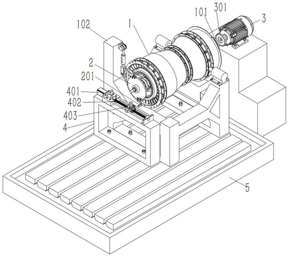
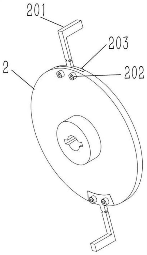
[0033] The present invention as Figure 1-4 As shown, it includes an installation stand 102 for installing the aero-engine rotor tester 1, a rotary drive assembly for driving and installing the aero-engine rotor tester 1, an L-shaped blade 201 for simulating blades, and an L-shaped blade for impacting. Impact system 4 of 201;

[0034] The L-shaped blade 201 is fixedly connected to the output shaft of the aero-engine rotor tester 1, and the ro...


PUM


Abstract

A simulation test device for the loss of an aeroengine rotor blade. It relates to the technical field of aeroengine blade loss test. A simulation test device for the loss of aeroengine rotor blades is proposed, which can effectively simulate the scene where the rotor blades are broken and fly out, and can effectively control the flying speed of the blades, so as to facilitate the simulation test of the rotor blade loss. It includes an installation stand 102 for installing the aero-engine rotor tester 1, a rotary drive assembly for driving and installing the aero-engine rotor tester 1, an L-shaped blade 201 for simulating a blade, and an impactor for hitting the L-shaped blade 201. System 4. Overall, the invention has the advantages of wide control range of blade loss speed, high precision, high structural similarity, strong operability, good repeatability, high safety and the like.

Description

technical field [0001] The invention relates to the technical field of aeroengine blade loss testing. Background technique [0002] Aeronautical gas turbine engine (referred to as "aero engine") is a high-speed rotating complex thermodynamic machinery. With the improvement of modern aero-engine's comprehensive requirements for high thrust-to-weight ratio and high performance, its speed and workload are constantly increasing and increasing. Presenting the mechanical characteristics of "softness" and "heavy load", the challenges faced by structural and dynamic design have increased significantly. In addition to satisfying the strength design under normal loads, it is also necessary to realize the safety design of the whole machine under extreme severe load conditions . [0003] Blade loss is a typical severe load condition that an aero-engine may encounter. It refers to a part or the entire rotor blade that breaks and flies out. It can be caused by bird strikes or other forei...

Claims


Application Information

Patent Timeline
Patent Type & Authority Patents(China)
IPC IPC(8): G01M15/14
CPCG01M15/14
Inventor 杨默晗陈果于平超张凯勇
Owner NANJING UNIV OF AERONAUTICS & ASTRONAUTICS
Why Eureka
Eureka Blog
Learn More