Unlock instant, AI-driven research and patent intelligence for your innovation.

Differential amplifier

A differential amplifier and differential input technology, applied in the direction of differential amplifiers, amplifiers, DC-coupled DC amplifiers, etc., to achieve the effect of reducing output voltage errors and reducing drift

Pending Publication Date: 2020-12-01
WINBOND ELECTRONICS CORP
View PDF0 Cites 0 Cited by
  • Summary
  • Abstract
  • Description
  • Claims
  • Application Information

AI Technical Summary

Problems solved by technology

Due to the non-ideal characteristics of components such as transistors and resistors in the cascaded differential amplifier 400, such as semiconductor process errors, the voltage conversion curve drifts, and the drift of the voltage conversion curve causes an output voltage error +Verr1 and output voltage error -Verr1

Method used


Image

  • Differential amplifier
  • Differential amplifier
  • Differential amplifier

Examples


Embodiment Construction

[0036] Hereinafter, embodiments of the present invention will be described with reference to the drawings.

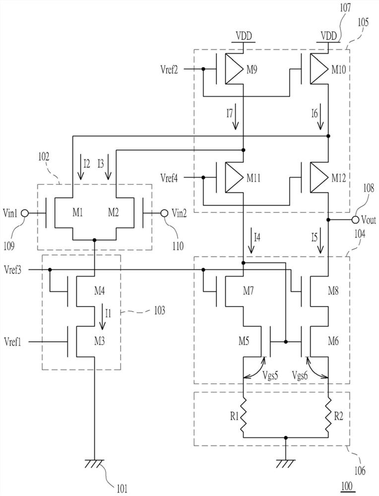
[0037] figure 1 is a circuit diagram showing a differential amplifier 100 according to an embodiment of the present invention.

[0038] The differential amplifier 100 of this embodiment includes a ground terminal 101, a differential input circuit 102, a first input terminal 109 and a second input terminal 110, a first current source circuit 103, a current mirror circuit 104, and a second current source circuit 105. , Impedance circuit 106, power supply terminal 107, output terminal 108.

[0039] Such as figure 1 As shown, the connection relationship of the above-mentioned components is as follows: the input of the first input terminal 109 of the differential input circuit 102 is the first input voltage Vin1, the input of the second input terminal 110 of the differential input circuit 102 is the second input voltage Vin2, the first The first terminal of the current ...


PUM


Abstract

The invention provides a differential amplifier, which comprises a differential input circuit for adjusting a second current and a third current flowing into the differential input circuit according to a first input voltage, a second input voltage and a first current; a first current source circuit which generates a first current according to a first reference voltage; a current mirror circuit which generates a fifth current according to the fourth current; a second current source circuit which generates a sixth current and a seventh current according to a second reference voltage; and an impedance circuit coupled between the current mirror circuit and a ground terminal, the differential amplifier having a low output voltage error.

Description

technical field [0001] The invention relates to a differential amplifier, in particular to a stacked differential amplifier. Background technique [0002] Cascaded differential amplifiers are widely used in unity-gain buffers due to their wide input and output voltage ranges, and are used to implement circuits such as impedance converters, voltage regulators, or comparators. Figure 4A It shows a schematic circuit diagram of a stacked differential amplifier 400 in the prior art, wherein Vin1, Vin2, Vout and VDD respectively represent a first input voltage, a second input voltage, an output voltage and a power supply voltage, Figure 4B Then it represents the voltage conversion curve of the difference between the first / second input voltage and the output voltage of the cascaded differential amplifier 400 . Due to the non-ideal characteristics of components such as transistors and resistors in the cascaded differential amplifier 400, such as semiconductor process errors, the v...

Claims


Application Information

Patent Timeline
IPC IPC(8): H03F1/30H03F3/45
CPCH03F1/301H03F3/45179
Inventor 大平信裕
Owner WINBOND ELECTRONICS CORP
Features
  • R&D
  • Intellectual Property
  • Life Sciences
  • Materials
  • Tech Scout
  • Unparalleled Data Quality
  • Higher Quality Content
  • 60% Fewer Hallucinations
Learn More