
High-strength automobile B column stamping die and stamping method

A stamping die, high-strength technology, applied in the field of auto parts processing, can solve the problems of increased automobile manufacturing cost, intrusion, and high cost of thermoforming molds, and achieves the effects of ensuring stability, reducing stamping difficulty, and improving yield.

Pending Publication Date: 2020-12-04
ANGANG STEEL CO LTD
View PDF9 Cites 1 Cited by
  • Summary
  • Abstract
  • Description
  • Claims
  • Application Information

AI Technical Summary

Problems solved by technology

When a car collides, especially in a side collision, the B-pillar will bear most of the impact force. If the B-pillar is not strong enough, the B-pillar will be deformed or broken during a side collision, and external objects will directly invade the passenger compartment, seriously threatening occupant's life safety
[0003] At present, some auto parts manufacturers use the thermoforming method to produce B-pillars. Due to the high cost of thermoforming molds, the cost of automobile manufacturing has increased significantly, which seriously affects the market promotion prospects and share of the car.
At present, many companies still use the cold stamping process to produce B-pillars, but due to the limitation of mold manufacturing technology, the strength level of parts is limited to about 590MPa, which cannot meet the requirements of modern body design.

Method used


Image

  • High-strength automobile B column stamping die and stamping method
  • High-strength automobile B column stamping die and stamping method
  • High-strength automobile B column stamping die and stamping method

Examples


Embodiment Construction

[0026] The invention discloses a high-strength automobile B-pillar stamping die and a stamping method. Those skilled in the art can refer to the content of this article to appropriately improve the process parameters to achieve. In particular, it should be pointed out that all similar replacements and modifications are obvious to those skilled in the art, and they are all considered to be included in the present invention. The method and application of the present invention have been described through preferred embodiments, and the relevant personnel can obviously make changes or appropriate changes and combinations to the method and application described herein without departing from the content, spirit and scope of the present invention to realize and Apply the technology of the present invention.

[0027] 【Example】

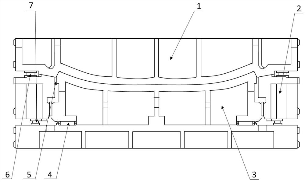
[0028] Such as figure 1 As shown, a high-strength automobile B-pillar stamping die includes an upper die 1, a blank holder 2 and a lower die 3, and through ...


PUM


Abstract

The invention relates to the technical field of automobile part machining, in particular to a high-strength automobile B column stamping die and a stamping method. The stamping die comprises an upperdie part, a blank holder and a lower die part, wherein the upper die part comprises an upper die base, a female die and an outer guide plate, the upper die part is fixed to the bottom of a press sliding block, the die surface of the female die corresponds to a B column in shape, and the outer guide plate guides the stroke of the upper die part; the blank holder comprises a locating key and a baffle and is used for carrying a to-be-stamped plate, and locating pins are arranged on the periphery of the blank holder and used for locating the to-be-stamped plate; a pressure adjusting pad is additionally arranged and used for adjusting the gap between the blank holder and the upper die part when the blank holder and the upper die part tightly press the plate, so that the feeding speed of the to-be-stamped plate is controlled; and the lower die part comprises a male die and a lower die base, the die face of the male die corresponds to the B column in shape, and the lower die base is fixedly connected to a press workbench. The stamping die is simple in structure and easy to operate, the manufacturing cost is lowered while the precision is guaranteed, and the stamping die can be applied to780MPa and 980MPa levels of automobile steel materials to complete stamping of automobile B column parts.

Description

technical field [0001] The invention relates to the technical field of automobile parts processing, in particular to a high-strength automobile B-pillar stamping die and a stamping method. Background technique [0002] The B-pillar of the car is the column between the front and rear doors of the car, which connects the roof and chassis of the car and plays a vital role in the strength of the side of the car. When a car collides, especially in a side collision, the B-pillar will bear most of the impact force. If the B-pillar is not strong enough, the B-pillar will be deformed or broken during a side collision, and external objects will directly invade the passenger compartment, seriously threatening safety of the occupants. [0003] At present, some auto parts manufacturers use thermoforming to produce B-pillars. Due to the high cost of thermoforming molds, the cost of auto manufacturing has increased significantly, which has seriously affected the market prospect and share ...

Claims


Application Information

Patent Timeline
IPC IPC(8): B21D37/10B21D22/02B21D43/00B21D53/88
CPCB21D22/02B21D37/10B21D43/003B21D53/88
Inventor 徐鑫刘仁东林利郝志强李春林梁笑吕冬丁庶炜陆晓锋芦延鹏
Owner ANGANG STEEL CO LTD
Learn More