
Full-servo electric upsetting machine and electric upsetting forming method

A technology of servo motor and forming method, which is applied to forging presses, forging presses, forging press driving devices, etc., can solve the problem of low operating speed and start-stop control accuracy of hydraulic cylinders, unstable strokes, length errors of cylinder parts, and heating temperature Problems such as within the setting range, to achieve the effect of ensuring upsetting effect, stable operation and small space occupation

Active Publication Date: 2022-07-22
TIANJIN PENGHU TECH
View PDF0 Cites 0 Cited by
  • Summary
  • Abstract
  • Description
  • Claims
  • Application Information

AI Technical Summary

Problems solved by technology

However, the existing electric upsetting machine has the following problems: 1. Adopting an oil cylinder (air cylinder) to push the middle of the slider, there will be deviations during installation, and the uneven force will cause the slider to have poor tilt stability; 2. During the upsetting process , because the speed of the ejector rod cannot be adjusted in real time, the upsetting temperature cannot always be within the set range of the heating temperature required for bar upsetting, the whole process cannot be detected, and the upsetting quality is poor; 3. The main clamp clamps The friction force of the bar is unpredictable, which leads to serious wear of the main clamp and reduces the service life; 4. The existing hydraulic electric upsetting machine is prone to oil leakage, needs regular oil change, and needs to install a hydraulic station, which has a large pneumatic volume and takes up space Large size, inconvenient replacement and maintenance, and low operating speed and start-stop control accuracy of the hydraulic cylinder; 5. The stroke is unstable when the pneumatic electric upsetting machine is working. The cylinder volume is large and the power is insufficient, and the length error of the processed parts is large.

Method used


Image

  • Full-servo electric upsetting machine and electric upsetting forming method
  • Full-servo electric upsetting machine and electric upsetting forming method
  • Full-servo electric upsetting machine and electric upsetting forming method

Examples


Embodiment Construction

[0029] In order to further understand the inventive content of the present invention, the present invention will be described in detail below with reference to specific embodiments.

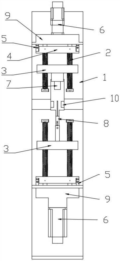
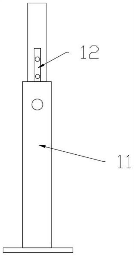
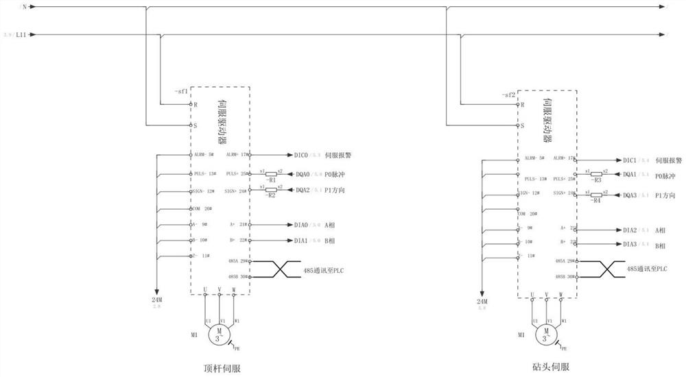
[0030] like Figure 1-4 As shown, an embodiment of the full-servo electric upsetting machine provided according to the present invention includes a frame 1 on which a bar clamping module 10 is installed, and a frame 1 above the bar clamping module 10 The anvil head driving mechanism is installed on the top, and the upsetting driving mechanism is installed on the frame 1 below the bar clamping module 10. The anvil head driving mechanism has the same structure as the upsetting driving mechanism, and the upsetting driving mechanism includes a sliding Block 3, pressure plate 4, transmission assembly, two ends of the slider 3 are respectively connected with a lead screw 2 threaded through, one end of the lead screw 2 is rotatably connected to the frame 1, and the other end of the lead screw 2 is conne...


PUM


Abstract

The invention relates to a full-servo electric upsetting machine and an electric upsetting forming method, comprising a frame, an anvil drive mechanism is installed on the frame above the bar clamping module, and a frame below the bar clamping module is installed on the frame. Install the upsetting drive mechanism. The upsetting drive mechanism includes a slider, a pressure plate, and a transmission assembly. The transmission assembly is installed on the frame. The pressure plate is located between the slider and the transmission assembly and is rotatably connected with the lead screw. Two pressure sensors are fixed between the pressing plate and the transmission assembly, and the two pressure sensors are respectively located at two ends of the bottom of the pressing plate. In the present invention, pressure sensors are respectively installed at both ends of the pressure plate corresponding to the anvil head, so that the pressure of the forming position formed by the anvil head and the bar can be detected in real time, so that the upward movement speed of the ejector rod can be adjusted to change the pressure value of the forming position, so as to ensure The temperature and pressure required for upsetting are within the preset temperature and pressure to ensure the upsetting effect.

Description

technical field [0001] The invention relates to the technical field of bar upsetting, in particular to a full-servo electric upsetting machine and an electric upsetting forming method. Background technique [0002] The electric upsetting process is to pass a low voltage and high current between the conductive clamping cylinder and the anvil cylinder to a slender alloy workpiece, so that the workpiece is heated to the plastic forming temperature by its own resistance. Upsetting. However, the existing electric upsetting machine has the following problems: 1. The oil cylinder (air cylinder) is used to push the middle of the slider, and there will be deviation during installation, and the uneven force will lead to poor inclination stability of the slider; 2. During the upsetting process , Because the speed of the ejector cannot be adjusted in real time, the upsetting temperature cannot always be within the set range of the heating temperature required for bar upsetting, the who...

Claims


Application Information

Patent Timeline
Patent Type & Authority Patents(China)
IPC IPC(8): B21J5/08B21J9/02B21J9/18B21J9/20G01L5/00
CPCB21J5/08B21J9/02B21J9/18B21J9/20G01L5/0028G01L5/0076
Inventor 牛永牛林涛
Owner TIANJIN PENGHU TECH
Learn More