Micro-pit electrolytic micro-bubble generator based on micro-drill hole making on electrode wall

A technology for micro-bubble generation and micro-pits, which is applied in transportation and packaging, ship hull, and ship construction, etc. problem, to achieve the effect of stable residence, improved residence rate, and high roundness

Active Publication Date: 2021-09-17
XIAMEN UNIV
View PDF0 Cites 0 Cited by
  • Summary
  • Abstract
  • Description
  • Claims
  • Application Information

AI Technical Summary

Problems solved by technology

At present, there are mainly the following technical bottlenecks for drag reduction technologies such as microbubble formation and residence control: microbubbles are mainly generated through ventilation, and the size of microbubbles generated by this method is difficult to control and consumes a lot of energy; at the same time, there are currently The technology of generating microbubbles through electrolysis has poor stability of the microbubbles generated on the surface of the vehicle, and it is difficult to control the growth of the microbubbles, and it is impossible to realize the self-adaptation when the microbubbles break or fall out of the pit. Therefore, in order to improve the range and speed of underwater vehicles, it is urgent to invent a new self-adaptive control microbubble drag reduction generating device based on micro-drill drilling, so as to realize timely and effective drag reduction in multi-scale and complex flow environments in water.

Method used


Image

  • Micro-pit electrolytic micro-bubble generator based on micro-drill hole making on electrode wall
  • Micro-pit electrolytic micro-bubble generator based on micro-drill hole making on electrode wall
  • Micro-pit electrolytic micro-bubble generator based on micro-drill hole making on electrode wall

Examples


Embodiment Construction

[0031] In order to make the technical problems, technical solutions and beneficial effects to be solved by the present invention clearer and clearer, the present invention will be further described in detail below in conjunction with the accompanying drawings and embodiments.

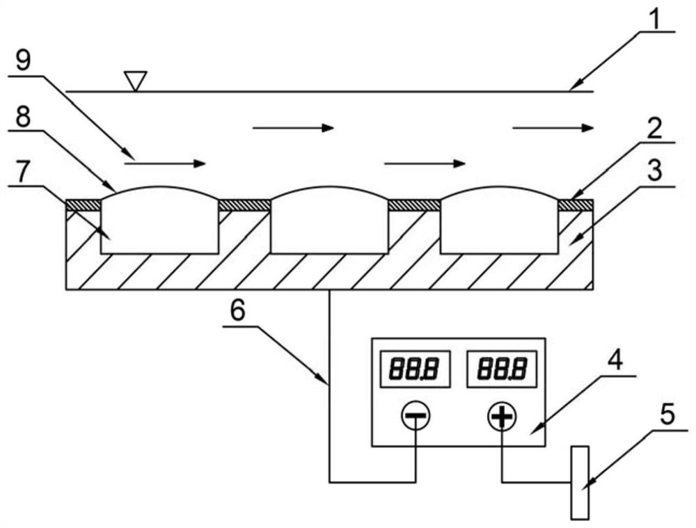
[0032] Such as figure 1 As shown, in this embodiment, the electrode wall micro-pit electrolytic micro-bubble generating device based on the micro-drill making holes includes a substrate 3, a DC stabilized power supply 4 and a carbon rod 5;

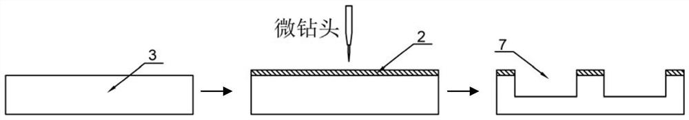
[0033] The base body 3 is made of metal copper sheet, and the surface of the base body 3 is evenly distributed or arranged at linearly increased intervals with cylindrical electrode wall micro-pits 7, the diameter of the electrode wall micro-pits 7 is 40-400 μm, and the depth is 20-200 μm ;

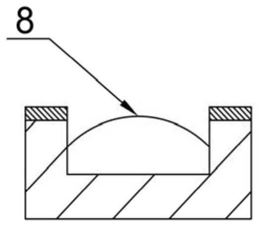
[0034] The upper surface of the substrate 3 is covered with a polyimide coating 2, and the material of the polyimide coating 2 is liquid polyimide; the micro pits 7 on the ele...


PUM

PropertyMeasurementUnit
diameteraaaaaaaaaa
depthaaaaaaaaaa
thicknessaaaaaaaaaa

Abstract

The invention relates to an electrolytic microbubble generating device based on a micro-drill-bit micro-pit electrolytic micro-bubble on the electrode wall, and relates to the technical field of active drag reduction of underwater vehicles. It includes a substrate, a carbon rod and a regulated DC power supply. The surface of the substrate is provided with a micro-pit structure on the electrode wall, the upper surface of the substrate is covered with a polyimide coating, and the lower surface of the substrate is connected to a regulated DC power supply through a power wire. The negative pole of the carbon rod is connected to the negative pole of the regulated DC power supply. By electrolyzing NaCl solution, the self-adaptive control of microbubble growth can be realized without continuous and long-term gas injection. When the microbubble breaks, falls off or the gas-liquid interface is lower than the laid polyimide coating, the device will automatically trigger The electrolytic circuit realizes adaptive control of micro-bubbles, and is suitable for surface ships and underwater vehicles; it can stably maintain micro-bubbles, which is beneficial to practical engineering and military applications.

Description

technical field [0001] The invention relates to the technical field of active drag reduction of underwater vehicles, in particular to an electrolytic micro-bubble generating device based on micro-pit electrolytic micro-bubbles on the electrode wall based on micro-drilling. Background technique [0002] The resistance of underwater vehicles is about 1,000 times that of aerial vehicles, which leads to the common defects of slow speed, short range and low precision in traditional underwater combat weapons. In order to increase the speed of underwater vehicles and improve the combat performance of underwater weapons, two technical approaches are generally adopted: increasing propulsion power and reducing navigational resistance. Because under normal circumstances, the speed of the aircraft can be doubled by increasing the thrust by eight times. However, the limited size of the aircraft limits the scale of the thrust device, so it is very difficult to significantly increase the ...

Claims


Application Information

Patent Timeline
Patent Type & Authority Patents(China)
IPC IPC(8): B63B1/38
CPCB63B1/38B63B2001/387Y02T70/10
Inventor 刘志荣朱睿庄启彬李尚张子捷吴德志
Owner XIAMEN UNIV
Why Eureka
Try Eureka