
Powdery fuel preheating gas generator and corresponding powdery fuel boiler

A pulverized fuel and generator technology, which is applied in the direction of granular/powdered fuel gasification, etc., can solve the problems that material balance is not easy to establish, material balance is not easy, and the operating elastic space is small, so as to achieve easy operation and improve safety and reliability The effect of large flexibility and operation space

Pending Publication Date: 2020-12-04
兖矿中科清洁能源科技有限公司
View PDF2 Cites 0 Cited by
  • Summary
  • Abstract
  • Description
  • Claims
  • Application Information

AI Technical Summary

Problems solved by technology

[0006] The technical problem to be solved by the present invention is how to overcome the small operating elastic space of the existing pulverized coal preheating burner and the corresponding vertical pulverized coal boiler, the difficulty in establishing the material balance during operation, and the difficulty in maintaining the material balance after the establishment of the material balance. to provide a powdery fuel preheating gas generator and corresponding powdery fuel boilers (including powdery fuel horizontal combustion boilers and powdery fuel vertical combustion boilers) with large operating flexibility space and long-term maintenance of material balance operation ), in order to improve the safety and reliability of boiler operation
This is the main reason why the existing pulverized coal preheating burner and vertical boiler have small elastic space, the material balance is not easy to establish during operation, and it is difficult to maintain the easy-to-run bottom material after the material balance is established.

Method used


Image

  • Powdery fuel preheating gas generator and corresponding powdery fuel boiler
  • Powdery fuel preheating gas generator and corresponding powdery fuel boiler
  • Powdery fuel preheating gas generator and corresponding powdery fuel boiler

Examples


Embodiment approach 1

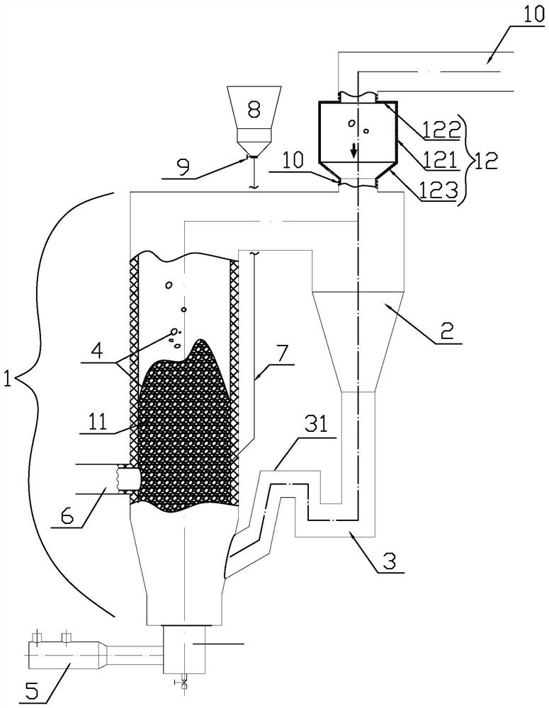
[0027] Implementation mode one: if figure 1 As shown, the pulverized fuel preheating gas generator of the present invention includes a preheating combustion chamber 1, a gas-solid separator 2 and a feeder 3, and the middle and lower part of the preheating combustion chamber 1 is provided with a fluidized bed 11 structure, and its interior The bottom material 4 of the fluidized bed is stored. The bottom of the preheating combustion chamber 1 is in the shape of an inverted cone. There are powder fuel feed pipe 6 and fluidized bed bottom feed pipe 7, the top of the fluidized bed bottom feed pipe 7 is provided with a feed hopper 8, and is provided with a feed valve 9, the gas-solid separator 2 is cyclone separation The gas-solid separator 2 is provided with an inlet, a lower solid outlet and a top gas outlet, the inlet of the gas-solid separator communicates with the top of the preheating combustion chamber 1, and the lower solid outlet of the gas-solid separator 2 is connected to...

Embodiment approach 2

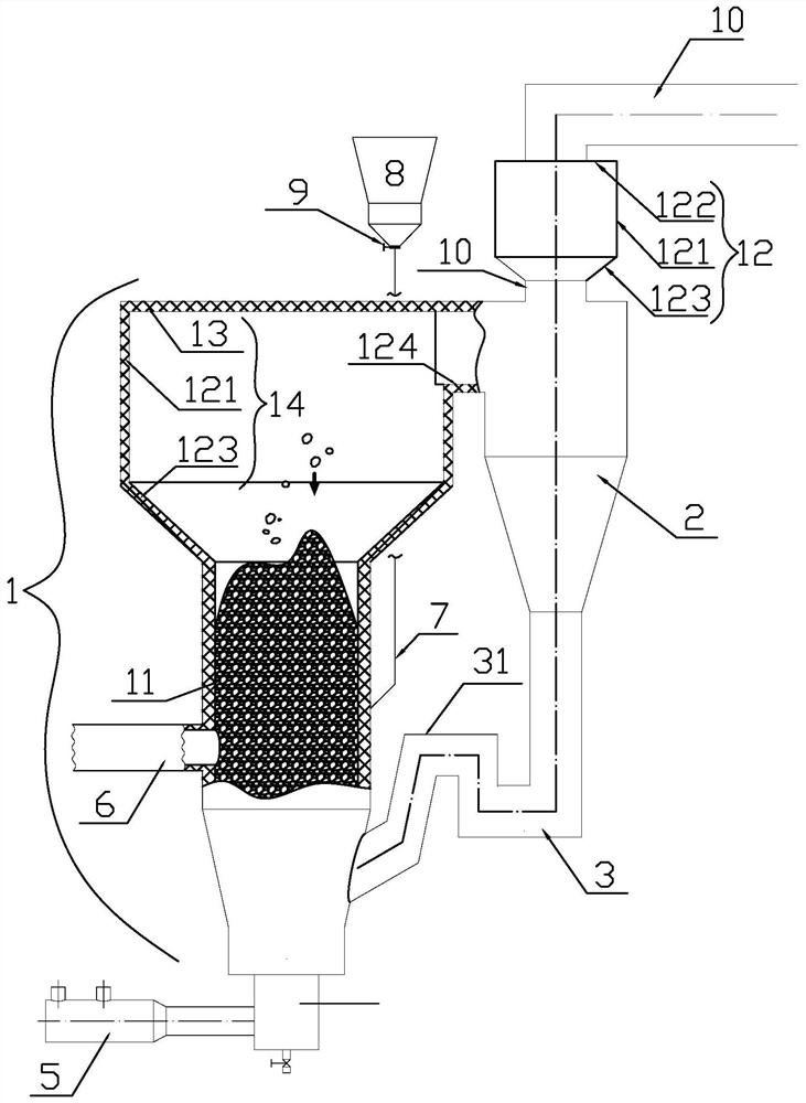
[0029] Implementation mode two: if figure 2 As shown, the upper part of the preheating combustion chamber 1 is also provided with a top sealing plate 13, an enlarged shell 121 and an inverted cone-shaped transition section 123. The expanded shell 121 is cylindrical, and its top side wall is provided with an air outlet Groove 124, the outer edge of the top sealing plate 13 is welded on the upper edge of the expansion shell 121 and the upper edge of the side wall of the air outlet groove 124, the top sealing plate 13 and the air outlet groove 124 form an air outlet, and pass through the air outlet Connected with the inlet of the gas-solid separator 2, the lower edge of the expanded casing 121 is welded to the outer edge of the large end of the inverted cone-shaped transition section 123, and the outer edge of the small end of the inverted-cone tubular transition section 123 is connected to the preheating combustion chamber 1. On the side wall of the fluidized bed 11 in the midd...

Embodiment approach 3

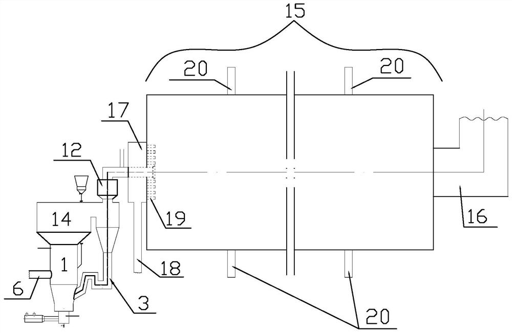
[0030] Implementation mode three: if image 3 As shown, the powder fuel horizontal combustion boiler of the present invention includes a horizontal boiler body 15, one end of the horizontal boiler body 15 is a feed end, the feed end is provided with a feed port, and the other end is provided with a tail flue 16, which The feature is that: the center of the side wall of the feed end of the horizontal boiler body 15 is provided with a secondary air box 17, and the exterior of the secondary air box 17 communicates with the secondary air pipe 18, and the interior of the horizontal boiler body 15 is provided with multiple The secondary air nozzle 19 connected to the secondary air box 17 is connected to the pulverized fuel preheating burner described in the first or second embodiment, omitted.

[0031] Implementation mode four: if image 3 As shown, the side wall of the horizontal boiler body 15 is provided with a plurality of embering air pipes 20, the above-mentioned embering air...


PUM


Abstract

The invention relates to a powdery fuel preheating gas generator and a corresponding powdery fuel boiler. An existing pulverized coal preheating burner and a corresponding boiler are small in operation elastic space, so that the pulverized fuel preheating gas generator comprises a preheating combustion chamber, a gas-solid separator and a return feeder, and further comprises an auxiliary gas-solidseparator which is arranged in the middle section of a gas outlet pipe connected with a gas outlet in the top of the gas-solid separator. The auxiliary gas-solid separator comprises an expanded shell, the area of the cross section of an inner cavity of the expanded shell is larger than or equal to 1.3 times that of the cross section of the gas outlet pipe, and the height of the expanded shell islarger than or equal to 0.5 m. And a gas-solid pre-separation chamber can be additionally arranged at the upper part of the preheating combustion chamber. The powdery fuel horizontal boiler comprisesa horizontal boiler body and a powdery fuel preheating burner. The powdery fuel preheating gas generator has the advantages of large operation elastic space, easiness in operation balance and easinessin maintenance after balance, and is suitable for various existing industrial and power station boilers.

Description

technical field [0001] The invention relates to a pulverized fuel preheating gas generator and a corresponding pulverized fuel boiler (including a pulverized fuel horizontal combustion boiler and a pulverized fuel vertical combustion boiler). Background technique [0002] The Chinese invention patent authorized on March 23, 2018 with the announcement number CN 104791775 B discloses a vertical pulverized coal boiler with a bottom burner. Combined waste heat boiler. [0003] The pulverized coal preheating burner disclosed in CN 104791775 B includes a preheating combustion chamber, a gas-solid separator and a feeder connected in sequence, and the three form a circulating fluidized bed gas generator. The vertical pulverized coal boiler has the advantages of sufficient combustion, small tail gas treatment burden, high efficiency, energy saving and environmental protection. [0004] The core of the pulverized coal preheating burner is a fluidized bed structure, in which quartz s...

Claims


Application Information

Patent Timeline
Patent Type & Authority Applications(China)
IPC IPC(8): C10J3/48C10J3/50
CPCC10J3/48C10J3/50
Inventor 潘清波张延亮赵宗花
Owner 兖矿中科清洁能源科技有限公司
Learn More