Aluminum plating device

A technology of aluminum plating and secondary plating, applied in sputtering plating, ion implantation plating, vacuum evaporation plating, etc.

Inactive Publication Date: 2020-12-04
张跃兵
View PDF0 Cites 5 Cited by
  • Summary
  • Abstract
  • Description
  • Claims
  • Application Information

AI Technical Summary

Problems solved by technology

[0005] In order to overcome that the vacuum thin film aluminum plating device in the prior art can only coat on one side, but many applications require double-sided coated sheet substrates. At this time, the vacuum thin film aluminum plating device in the prior art can only coat on one side respectively. The processing efficiency is low due to two-time coating, which cannot meet the production needs. Some double-sided coating equipment can perform one-time double-sided coating, but it does not cool and solidify the aluminum-plated plastic film after one coating. Subsequent secondary aluminum plating treatment is directly carried out, so that the aluminum layer on one side of the plastic film has not been solidified, and the unsolidified surface of the aluminum layer is directly in contact with the next conveying roller, resulting in the uncooled and solidified aluminum layer on the surface Damaged, resulting in uneven damage to the aluminum-coated film. At the same time, there is a phenomenon that the plastic film is not tightened during the coating process, resulting in misalignment and distortion of the plastic film during transmission, resulting in dislocation of the coating film. Part of the aluminum vapor will be sprayed to the exposed positions on both sides of the conveying roller that is not covered by plastic film, which will cause the accumulation of aluminum layers on both sides of the conveying roller to become thicker and thicker, which will affect the shortcoming of subsequent use. The technical problem of the present invention is to provide a Aluminum device

Method used


Image

  • Aluminum plating device
  • Aluminum plating device
  • Aluminum plating device

Examples


Embodiment 1

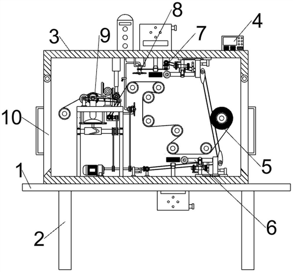
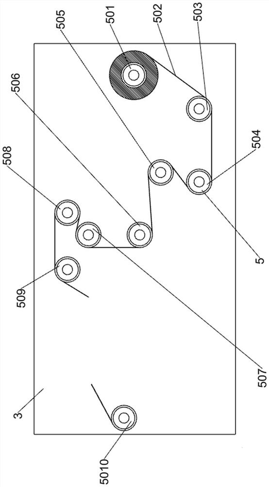
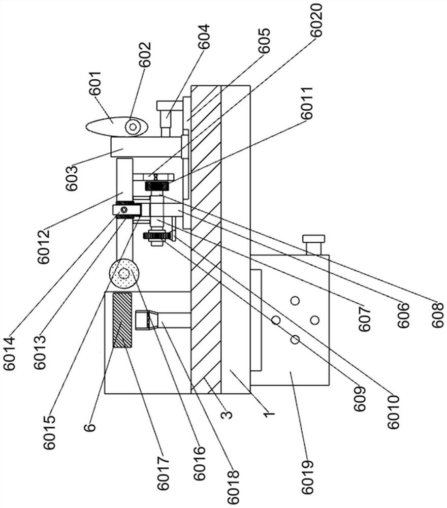
[0029] An aluminum plating device such as Figure 1-7As shown, it includes a working machine plate 1, a supporting foot 2, a processing cabin 3, an operation control panel 4, a transmission roller mechanism 5, a primary aluminum plating mechanism 6, a secondary aluminum plating mechanism 7, a cooling and solidification mechanism 8, and a fastness The detection mechanism 9 is connected to the cabin door 10; the lower part of the working machine tool board 1 is welded with the support foot 2; the upper part of the working machine tool board 1 is welded with the processing cabin 3; the upper part of the processing cabin 3 is provided with an operation control panel 4; the processing cabin 3 is connected with the connecting cabin door 10; the processing cabin body 3 is connected with the conveying roller mechanism 5; the processing cabin body 3 is connected with the primary aluminum plating mechanism 6; the processing cabin body 3 is connected with the secondary aluminum plating me...


PUM


Abstract

The invention relates to the field of aluminum plating, in particular to an aluminum plating device. The aluminum plating device is provided to solve the technical problem. Based on the technical scheme, the aluminum plating device comprises a conveying roller mechanism, a primary aluminum plating mechanism, a secondary aluminum plating mechanism, a cooling and solidification mechanism, a fastnessdetection mechanism, a communication cabin door and the like, and the lower portion of a working machine tool plate is welded to supporting bottom feet. According to the aluminum plating device, double-sided aluminum plating of a plastic film is achieved, aluminum on the surface of the plastic film is rapidly cooled and solidified after one side of the plastic film is aluminized, then aluminum plating operation is conducted on the other side of the plastic film, and then rapid cooling and solidification are conducted again, so that the plastic film is ensured to be in a tensioned state all the time in the aluminum plating process so as not to be misplaced, meanwhile, aluminum plating on two sides of a conveying roller in the device by means of aluminum steam is avoided, and the effect ofrespectively detecting the fastness of aluminum layers on two surfaces of the plastic film after rapid cooling and solidification is achieved.

Description

technical field [0001] The invention relates to the field of aluminum plating, in particular to an aluminum plating device. Background technique [0002] Aluminum-coated film is a bright metallic film formed by evaporating high-purity aluminum wire into a gaseous state at high temperature through a vacuum aluminum-plating process, and then when the plastic film passes through a vacuum evaporation chamber, the gaseous aluminum molecules precipitate on the surface of the plastic film. [0003] At present, the vacuum thin-film aluminum plating device in the prior art can only coat on one side, but many applications require sheet substrates with double-sided coating. At this time, the vacuum thin-film aluminum plating device in the prior art can only coat on one side respectively. The processing efficiency is low due to two-time coating, which cannot meet the production needs. Some double-sided coating equipment can perform one-time double-sided coating, but it does not cool and...

Claims


Application Information

Patent Timeline
Patent Type & Authority Applications(China)
IPC IPC(8): C23C14/56C23C14/24C23C14/20C23C14/58
CPCC23C14/20C23C14/24C23C14/562C23C14/58
Inventor 张跃兵
Owner 张跃兵
Why Eureka
Try Eureka