PCB (printed circuit board) pre-welding device and method and circuit board welding equipment

A PCB circuit board and circuit board technology, which is applied in the field of circuit board welding equipment and PCB circuit board pre-soldering device, can solve the problems of many welding steps and low welding efficiency, so as to improve efficiency, facilitate connection and welding, and improve transmission efficiency Effect

Inactive Publication Date: 2021-09-03
郑晓静
View PDF7 Cites 4 Cited by
  • Summary
  • Abstract
  • Description
  • Claims
  • Application Information

AI Technical Summary

Problems solved by technology

[0005] The purpose of the present invention is to propose a PCB circuit board pre-soldering device and its welding method with simultaneous automatic feeding and high welding efficiency for the problems of many welding steps and low welding efficiency between the circuit board and the wire in the prior art

Method used


Image

  • PCB (printed circuit board) pre-welding device and method and circuit board welding equipment
  • PCB (printed circuit board) pre-welding device and method and circuit board welding equipment
  • PCB (printed circuit board) pre-welding device and method and circuit board welding equipment

Examples


Embodiment Construction

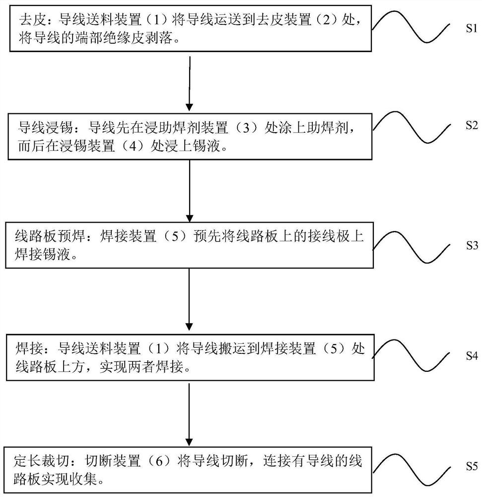
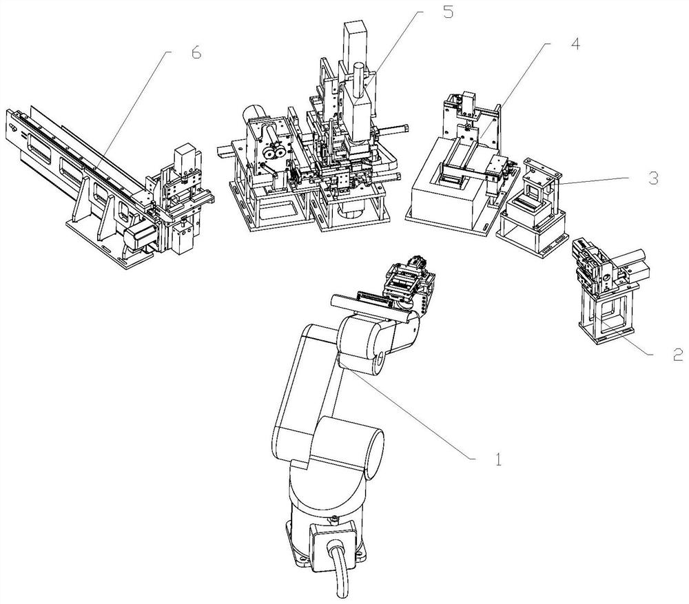
[0030] Such as figure 2 As shown, a PCB circuit board welding equipment includes a frame and a wire feeding device 1 installed on the frame, a peeling device 2, a flux dipping device 3, a tin dipping device 4, a welding device 5 and a cutting device 6. The wire feeding device 1 described above is arranged in the middle of the frame, and the peeling device 2, the flux dipping device 3, the tin dipping device 4, the welding device 5 and the cutting device 6 are arranged around the wire feeding device 1 sequentially in an arc shape. , the above-mentioned devices all correspond to the wire feeding device 1.

[0031] The wire feeding device 1 is used for feeding wires, and transporting the wires between various stations for transfer, the peeling device 2 is used for peeling the ends of the wires, the flux immersion device 3 and the tin immersion device 4 Soldering flux and tin wire are respectively melted and wrapped on the exposed ends of the wires. The welding device 5 is used ...


PUM


Abstract

The invention discloses a PCB (printed circuit board) prewelding device. The prewelding device comprises a first base, a tin wire feeding assembly, a circuit board feeding assembly, a second base, a circuit board feeding rail, a circuit board pushing assembly, a lifting base assembly, a traction assembly, a wire pressing assembly and a welding assembly, the tin wire feeding assembly and the circuit board feeding assembly are arranged on the first base, the second base is arranged on the side of the first base, the circuit board feeding rail is fixedly arranged on the second base and is connected to the side of the circuit board feeding assembly, the lifting seat assembly is connected to the circuit board feeding rail, the wire pressing assembly corresponds to the upper portion of the circuit board feeding rail, the traction assembly is arranged on the second base, the traction assembly corresponds to the wire pressing assembly from the side, the circuit board pushing assembly is connected to the circuit board feeding assembly and the circuit board feeding rail, and the welding assembly is arranged on the second base and corresponds to the lifting base assembly from top to bottom. The prewelding device has the advantages that materials are fed simultaneously, and the welding efficiency is high.

Description

technical field [0001] The invention relates to the field of electronic component production, in particular to a PCB circuit board pre-welding device, a welding method thereof, and circuit board welding equipment. Background technique [0002] With the continuous advancement of science and technology, people use technology products more and more frequently. Among them, electronic and computer products are the most important tools for use. The above-mentioned products are all composed of different circuit boards, and each circuit board Solder the connectors separately on the top and then insert the flexible flat cable to connect them for data transmission. Because the soft flat cable with smaller specifications is not easy to assemble and control electromagnetic interference, the material for controlling electromagnetic interference is hard and not easy to bend. Therefore, there has been a connection method of directly soldering the wires on the circuit board. At present, the...

Claims


Application Information

Patent Timeline
Patent Type & Authority Applications(China)
IPC IPC(8): B23K1/08B23K1/20B23K3/00B23K3/06B23K3/08H05K3/34B23K101/42
CPCB23K3/00B23K3/063B23K3/08H05K3/34B23K1/20B23K1/08B23K3/087B23K2101/42
Inventor 郑晓静唐安安李桂国
Owner 郑晓静
Why Eureka
Try Eureka