
Dyeing device for textile fabric processing

A dyeing device and technology for textile fabrics, applied in textile processing machine accessories, equipment configuration for processing textile materials, processing of textile materials, etc., can solve the problem of high cost and achieve the effect of low cost

Pending Publication Date: 2020-12-04
绍兴和为贵机械科技有限公司
View PDF3 Cites 0 Cited by
  • Summary
  • Abstract
  • Description
  • Claims
  • Application Information

AI Technical Summary

Problems solved by technology

[0002] Cloth is a common raw material for making clothes. Due to the different patterns on the clothes, it needs to dye the different patterns on the clothes during the production process. In the process of dyeing, the existing processing method is to use a bracket to The cloth is supported, and then the cloth is put into the dye vat, and then soaked. The cost is high, and it is not suitable for the processing of cloth with complicated patterns.

Method used


Image

  • Dyeing device for textile fabric processing
  • Dyeing device for textile fabric processing
  • Dyeing device for textile fabric processing

Examples


Embodiment

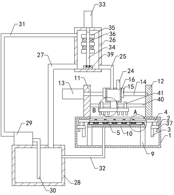
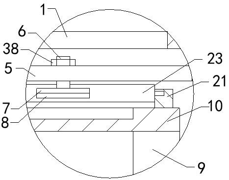
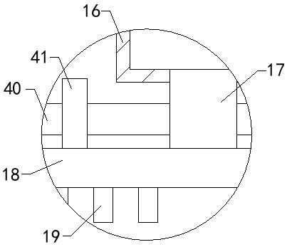
[0025] see Figure 1-5, a dyeing device for textile fabric processing, comprising a support box 1, the left end of the inner wall of the support box 1 and the right end of the inner wall are fixedly connected with cantilever plates 2, the bottom ends of each cantilever plate 2 are equipped with cylinders 3, the output of each cylinder 3 The shaft ends pass through the cantilever plate 2 from the bottom of the cantilever plate 2 and protrude from the upper side of the cantilever plate 2. The output shaft ends of each cylinder 3 are fixedly connected with a connecting plate 4, and the bottom ends of the connecting plate 4 are fixedly connected. There are sliding shafts 37, and the bottom ends of each sliding shaft 37 pass through the cantilever plate 2 from the top of the cantilever plate 2; through the cooperation of the sliding shaft 37 and the cantilever plate 2, the movement posture of the connecting plate 4 is limited, and the limit plate 41 is reduced. And the deformation ...


PUM


Abstract

The invention relates to the technical field of textile fabric processing, in particular to a dyeing device for textile fabric processing. The dyeing device comprises a supporting box, cantilever plates are fixedly connected to the left end and the right end of the inner wall of the supporting box correspondingly, and an air cylinder is installed at the bottom end of each cantilever plate. The output shaft end of each air cylinder penetrates through the corresponding cantilever plate from the bottom end of the corresponding cantilever plate and extends out of the upper side of the corresponding cantilever plate, the output shaft end of each air cylinder is fixedly connected with a connecting plate, the opposite end of each connecting plate is fixedly connected with a frame plate, a plurality of sets of screw rods are screwed in the middle of each frame plate, and the bottom end of each screw rod is fixedly connected with a sealing plate. A pressing plate is fixedly connected to the bottom end of each sealing plate, supporting plates are fixedly connected to the left portion and the right portion of the bottom end of the inner wall of the supporting box correspondingly, a top plateis arranged in the supporting box, the left portion and the right portion of the bottom end of the top plate are fixedly connected with the top ends of the corresponding supporting plates correspondingly, and a storage groove is formed in the top end of the top plate. The dyeing device is low in cost and suitable for processing of a fabric with complex patterns.

Description

technical field [0001] The invention relates to the technical field of textile cloth processing, in particular to a dyeing device for textile cloth processing. Background technique [0002] Cloth is a common raw material for making clothes. Due to the different patterns on the clothes, it needs to dye the different patterns on the clothes during the production process. In the process of dyeing, the existing processing method is to use a bracket to The cloth is supported, then the cloth is put into the dye vat, and then soaked, the cost is high, and it is not suitable for the processing of cloth with more complicated patterns. Contents of the invention [0003] (1) Solved technical problems [0004] Aiming at the deficiencies of the prior art, the invention provides a dyeing device for textile fabric processing with low cost and suitable for fabric processing with complex patterns. [0005] (2) Technical solutions [0006] In order to achieve the above object, the presen...

Claims


Application Information

Patent Timeline
Patent Type & Authority Applications(China)
IPC IPC(8): D06B1/02D06B15/00D06B23/04D06B23/20
CPCD06B1/02D06B23/04D06B15/005D06B23/205D06B23/20
Inventor 宋洪岩
Owner 绍兴和为贵机械科技有限公司
Learn More