Pressing valve and water discharging faucet

A water outlet and valve stem technology, applied to valve details, multi-way valves, valve devices, etc., can solve problems such as inability to switch water channels, poor pressing feel, and pilot hole failure, so as to ensure the pressing feel, reduce resistance, and eliminate The effect of force

Pending Publication Date: 2020-12-04
FUJIAN XIHE SANITARY WARE TECH
View PDF0 Cites 0 Cited by
  • Summary
  • Abstract
  • Description
  • Claims
  • Application Information

AI Technical Summary

Problems solved by technology

[0002] Existing push valves generally include a valve housing, a valve stem, a diaphragm, and a push assembly. The push assembly is usually a ballpoint pen press structure. Through the cooperation of the ratchet and ratchet teeth, the ratchet is pushed to rotate at a certain angle and stops at two positions when pressing. Between, so that the valve stem can be positioned at the preset position, the pilot hole is set on the diaphragm, and the water flow is pre-injected through the pilot hole to make the water pressure of the chambers on both sides of the diaphragm consistent, thereby reducing the resistance when pressing , to ensure the pressing feel, but this kind of pilot-operated pressing valve is prone to failure due to the blockage of the pilot hole, and it is impossible to switch the waterway. In order to solve this problem of the pilot-operated pressing valve, there is a direct use of pressing components to push the valve stem The push valve structure slides to switch the waterway, but this structure leads to the need to overcome the water pressure when pressing, resulting in poor pressing feel

Method used

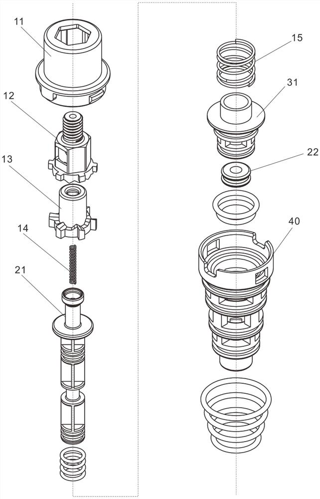
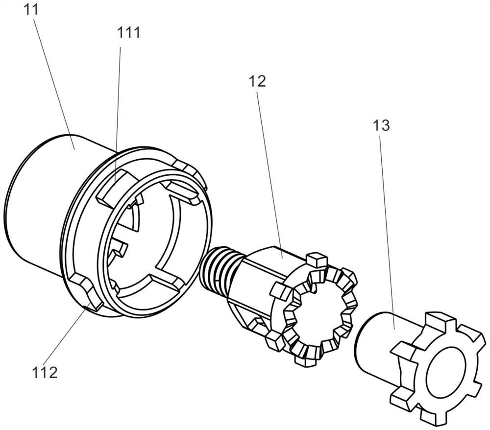
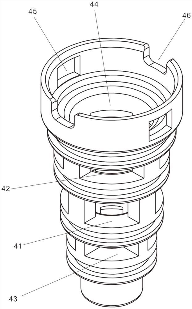

Image

  • Pressing valve and water discharging faucet
  • Pressing valve and water discharging faucet
  • Pressing valve and water discharging faucet

Examples


Embodiment Construction

[0039] The following will clearly and completely describe the technical solutions in the embodiments of the present invention with reference to the drawings in the embodiments of the present invention. Obviously, the described embodiments are preferred embodiments of the invention and should not be seen as excluding other embodiments. Based on the embodiments of the present invention, all other embodiments obtained by persons of ordinary skill in the art without creative efforts fall within the protection scope of the present invention.

[0040] In the claims, description and above-mentioned drawings of the present invention, unless otherwise clearly defined, the terms "first", "second" or "third" are used to distinguish different objects, not for Describe a specific order.

[0041] In the claims, specification and above-mentioned drawings of the present invention, unless otherwise clearly defined, for orientation words, such as using the terms "center", "transverse", "longit...


PUM


Abstract

The invention discloses a pressing valve and a water discharging faucet. The pressing valve comprises a valve shell, a valve rod and a pressing assembly, the valve rod is driven by the pressing assembly to slide between a first position and a second position in the axial direction of the valve shell so as to switch the water discharging state or the water filling state of the valve shell, and thevalve rod is provided with two sets of pressure bearing structures in the axial direction of the valve rod. Each set of pressure bearing structures comprises two pressure bearing surfaces which are oppositely arranged and have the same pressure-bearing area; and when the valve rod is positioned at the first position or the second position, the corresponding set of pressure bearing structures bearwater. By adopting the pressing valve and the water discharging faucet with the structure, the pressure of water pressure on the valve rod can form balance, so that the resistance during pressing operation is reduced, and the pressing hand feeling of the pressing valve is ensured.

Description

technical field [0001] The invention relates to the technical field of valves, in particular to a push valve and a water outlet faucet. Background technique [0002] Existing push valves generally include a valve housing, a valve stem, a diaphragm, and a push assembly. The push assembly is usually a ballpoint pen press structure. Through the cooperation of the ratchet and ratchet teeth, the ratchet is pushed to rotate at a certain angle and stops at two positions when pressing. Between, so that the valve stem can be positioned at the preset position, the pilot hole is set on the diaphragm, and the water flow is pre-injected through the pilot hole to make the water pressure of the chambers on both sides of the diaphragm consistent, thereby reducing the resistance when pressing , to ensure the pressing feel, but this kind of pilot-operated pressing valve is prone to failure due to the blockage of the pilot hole, and it is impossible to switch the waterway. In order to solve th...

Claims


Application Information

Patent Timeline
Patent Type & Authority Applications(China)
IPC IPC(8): F16K11/044F16K31/56F16K27/02F16F15/067
CPCF16K11/044F16K31/56F16K27/0263F16F15/067F16K11/0445F16K31/52416F16K39/022
Inventor 林孝发林孝山刘启乔邓小清余开石
Owner FUJIAN XIHE SANITARY WARE TECH
Why Eureka
Try Eureka