Large-span concrete beam multi-point continuous measurement device and measurement method

A technology of concrete beams and measuring devices, which is applied in the direction of measuring devices, measuring force, and optical devices, etc., can solve the problems of difficulty in ensuring the safe operation of inspectors, unsuitable continuous measurement of long-span beams, and high requirements for inspectors. Test results, improve the ability to resist local large deformation, and ensure the effect of flexibility

Pending Publication Date: 2020-12-04
THE 4TH ENG OF CHINA RAILWAY 5TH ENG GROUP +2
View PDF0 Cites 0 Cited by
  • Summary
  • Abstract
  • Description
  • Claims
  • Application Information

AI Technical Summary

Problems solved by technology

[0003] At present, for the traditional monitoring of long-span beam structures in large-scale hub structures, point strain gauges, electromagnetic induction or manual inspection methods are generally used. Disadvantages that it is difficult to guarantee the safety of personnel
Compared with traditional conventional sensors, optical fiber sensing technology has good anti-electromagnetic interference ability, can realize large-scale and long-distance real-time monitoring, avoid the irrationality of human experience judgment, and greatly reduce missed detection and false alarm The probability of providing timely and accurate important information; but at present, fiber gratings are mostly packaged into single-point strain gauges, which can only detect one area, and are not suitable for continuous measurement of multiple points on long-span beams.

Method used


Image

  • Large-span concrete beam multi-point continuous measurement device and measurement method
  • Large-span concrete beam multi-point continuous measurement device and measurement method
  • Large-span concrete beam multi-point continuous measurement device and measurement method

Examples


Embodiment Construction

[0028] The following will clearly and completely describe the technical solutions in the embodiments of the present invention in conjunction with the accompanying drawings in the embodiments of the present invention. Obviously, the described embodiments are only some of the embodiments of the present invention, not all of them. Based on the embodiments of the present invention, all other embodiments obtained by persons of ordinary skill in the art without making creative efforts belong to the protection scope of the present invention. In addition, all the connection relationships mentioned in this article do not refer to the direct connection of components, but mean that a better connection structure can be formed by adding or reducing connection accessories according to the specific implementation situation.

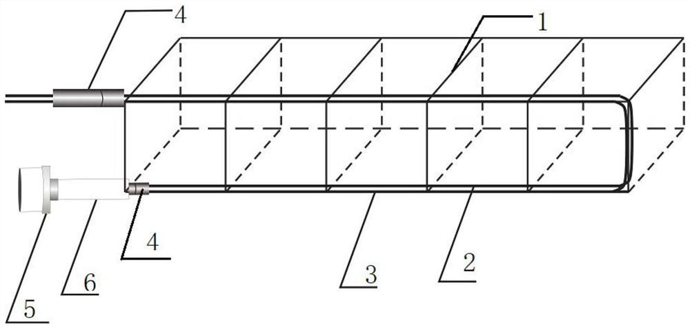
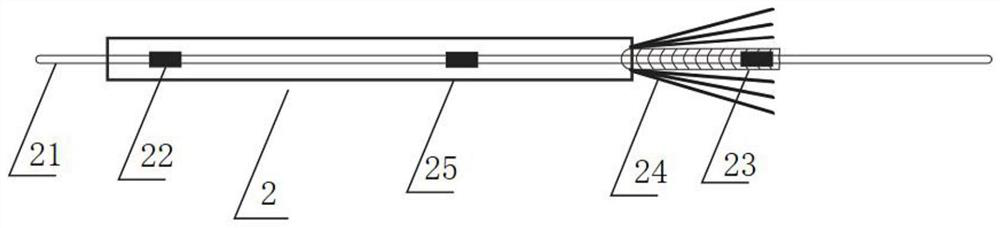
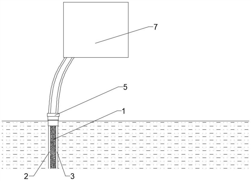
[0029] see Figure 1-3 As shown, a multi-point continuous measurement device for large-span concrete beams includes an internal fixed-point strain optical cable 2, a st...


PUM


Abstract

The invention discloses a large-span concrete beam multi-point continuous measurement device and a measurement method. The device comprises an inner fixed point type strain optical cable, a reinforcement cage and an optical fiber and optical cable demodulator, wherein the inner fixed point type strain optical cable is bound on a main reinforcement of the reinforcement cage and is poured into the concrete beam; the inner fixed point type strain optical cable is connected to the optical fiber and optical cable demodulator; the internal fixed point type strain optical cable comprises an optical cable inner core, internal fixed point FBG sensors, an optical cable sheath, an armor tube and a steel strand. The plurality of internal fixed point FBG sensors are uniformly distributed in the opticalcable inner core and are wrapped in the armor tube; the optical cable sheath wraps the armor tube wound with the plurality of strands of steel strands; the number of the inner fixed point FBG sensorsof a single inner fixed point type strain optical cable reaches 2000, and multi-point dense continuous testing of a large-span concrete structure is achieved. The temperature sensing optical cable and the inner fixed point type strain optical cable are symmetrically distributed up and down along the main reinforcements of the reinforcement cage; the optical fiber and optical cable demodulator canobtain a plurality of data at the same time, thereby achieving the monitoring of the internal force, bending moment and deflection of the concrete beam.

Description

technical field [0001] The invention relates to the monitoring field of long-span concrete beams, in particular to a multi-point continuous measuring device and a measuring method for long-span concrete beams. Background technique [0002] Optical fiber sensing technology is a new type of sensing technology that uses light as the carrier and optical fiber as the medium to perceive and transmit external signals, which developed rapidly with the development of optical fiber and optical fiber communication technology in the 1980s. It is used in all aspects of civil engineering. [0003] At present, for the traditional monitoring of long-span beam structures in large-scale hub structures, point strain gauges, electromagnetic induction or manual inspection methods are generally used. The shortcoming that it is difficult to guarantee the safe operation of personnel. Compared with traditional conventional sensors, optical fiber sensing technology has good anti-electromagnetic int...

Claims


Application Information

Patent Timeline
Patent Type & Authority Applications(China)
IPC IPC(8): G01D21/02G01B11/16G01L1/24G01L3/00
CPCG01B11/16G01D21/02G01L1/242G01L3/00
Inventor 廖令军戴勇莫成汪阳刘兰其张继清张浩亮侯靖宇费瑞振王林辉王彦伟焦忺玥曹纯博魏广庆王宏宪贾立翔
Owner THE 4TH ENG OF CHINA RAILWAY 5TH ENG GROUP
Why Eureka
Try Eureka