
Linear correction positioning method and system of acoustic emission source with unknown wave velocity, and storage medium

A technology of acoustic emission source and positioning method, which is applied in the direction of radio wave measurement system, positioning, measuring device, etc., and can solve the problems of low calculation efficiency and inaccurate positioning of acoustic emission source

Active Publication Date: 2020-12-04
CENT SOUTH UNIV
View PDF9 Cites 2 Cited by
  • Summary
  • Abstract
  • Description
  • Claims
  • Application Information

AI Technical Summary

Problems solved by technology

[0003] The present invention provides an acoustic emission source linear correction positioning method, system and storage medium with unknown wave velocity to solve the problem of inaccurate acoustic emission source positioning and calculation in related technologies The problem of inefficiency

Method used


Image

  • Linear correction positioning method and system of acoustic emission source with unknown wave velocity, and storage medium
  • Linear correction positioning method and system of acoustic emission source with unknown wave velocity, and storage medium
  • Linear correction positioning method and system of acoustic emission source with unknown wave velocity, and storage medium

Examples


Embodiment 1

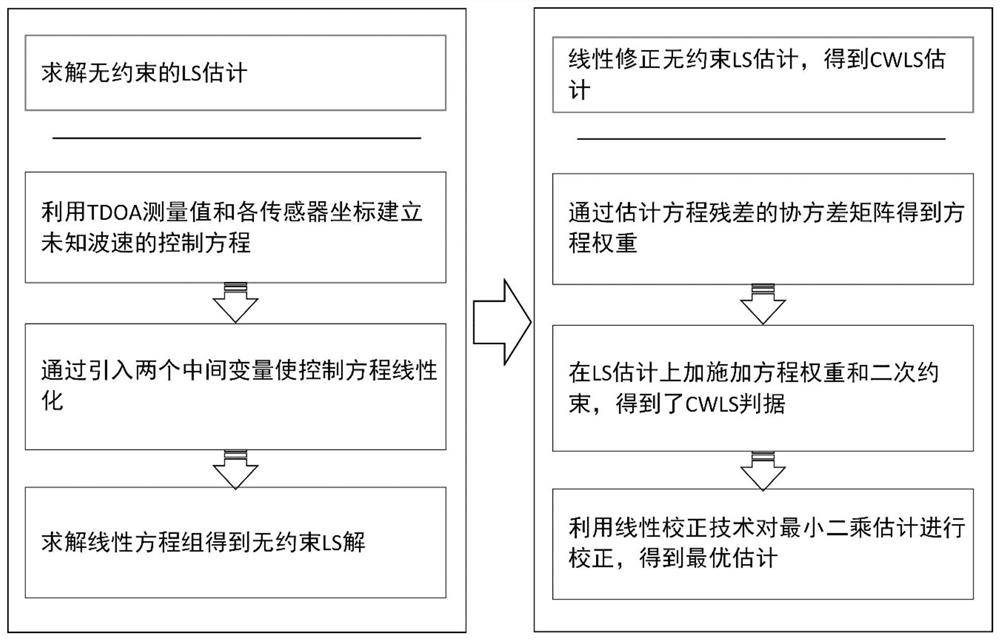
[0100] Such as figure 1 As shown, this embodiment provides a linear correction positioning method for an acoustic emission source with unknown wave velocity, including:

[0101] S01: Select a sensor from multiple sensors as a reference sensor; construct the TDOA equation of unknown wave velocity according to the reference sensor, and obtain a linear equation system by introducing two intermediate variables V and K; solve the linear equation system to obtain an unconstrained least squares Multiply (LS) solution; where V=v 2 , v represents the propagation velocity of the acoustic emission signal, and x, y, and z are the components of the coordinates of the acoustic emission source respectively; where the sensor is an acoustic emission or microseismic sensor;

[0102] S02: Obtain the weight matrix of the linear equation system by estimating the residual error of the equation;

[0103] S03: Apply the weight matrix and quadratic constraints to the least squares (LS) estimation ...

Embodiment 2

[0107] In this embodiment, on the basis of Embodiment 1, in the step S01, the coordinates of the reference sensor are set to (0, 0, 0), then the expressions of the linear equations are as follows:

[0108]

[0109] Among them, x, y, z are the components of the coordinates of the acoustic emission source, and x i 、y i ,z i represent the coordinate components of the i-th sensor respectively, t i,0 represents the TDOA measurement value between the i-th sensor and the reference sensor, and M represents the number of sensors; in this embodiment, M≥6, and M sensors are not all coplanar.

[0110] The least squares (LS) solution is:

[0111]

[0112] in The symbol T in the upper right corner means matrix transpose.

Embodiment 3

[0114] In this embodiment, on the basis of Embodiment 2, in the step S02, the weight matrix is:

[0115] W=(4BNB) -1

[0116] in, means t i,0 Items that do not contain noise; in the weight matrix W, unknown parameters be t i,0 replaced by ; in addition, the unknown parameters K and V are respectively replaced by θ 0 (4) and θ 0 (5) Approximate substitution, where θ 0 (4) and θ 0 (5) represent the least squares solution θ respectively 0 The fourth and fifth elements of .


PUM


Abstract

The invention discloses a linear correction positioning method and system of an acoustic emission source with an unknown wave velocity, and a storage medium. The method comprises the following steps:constructing a linear equation set of the unknown wave velocity through introducing two intermediate variables, and solving an unconstrained least square (LS) solution; obtaining a weight matrix of the equation set by estimating an equation residual error; applying the weight matrix and the quadratic constraint to least square (LS) estimation by using a Lagrange multiplier technology to constructa Lagrange function; minimizing the Lagrange function to obtain a new nonlinear equation set; and solving the nonlinear equation set by adopting a linear correction technology so as to obtain optimalestimation. The method and the system are high in positioning precision and high in calculation speed.

Description

technical field [0001] The invention relates to the technical field of non-destructive testing, in particular to a method, system and storage medium for linearly correcting and locating an acoustic emission source with unknown wave velocity. Background technique [0002] As an important non-destructive testing technique, acoustic emission is widely used in rock mechanics and mining engineering. Acoustic emission source location technology can determine the exact location of fractures and faults, so it is often used as a scientific basis for studying the mechanism of crack initiation and propagation and evaluating the risk of rockburst. TDOA (Time Difference of Arrival) measurements based on spatially separated sensors have superior performance and are therefore widely used. There are many existing acoustic emission source localization methods based on TDOA measurement data, but all of these methods need to measure the wave velocity in advance. If the wave velocity measureme...

Claims


Application Information

Patent Timeline
Patent Type & Authority Applications(China)
IPC IPC(8): G01S5/22
CPCG01S5/22
Inventor 周子龙芮艺超蔡鑫陆建友蓝日彦
Owner CENT SOUTH UNIV
Learn More