
Computer radiator utilizing cyclone centrifugal separation

A centrifugal separation and cyclone separation technology, which is applied in computing, machines/engines, components of pumping devices for elastic fluids, etc., can solve problems affecting CUP work, CUP damage, time-consuming and labor-intensive problems, and improve the overall service life , improve the service life, improve the effect of cooling efficiency

Inactive Publication Date: 2020-12-04
杭州郜灵科技有限公司
View PDF8 Cites 0 Cited by
  • Summary
  • Abstract
  • Description
  • Claims
  • Application Information

AI Technical Summary

Problems solved by technology

[0005] Aiming at the deficiencies of the prior art, the present invention provides a computer heat sink using cyclone centrifugal separation, which is capable of centrifugally separating the dust in the air by using the cyclone, separating the air from the dust, reducing the possibility of dust entering the cooling fins and simultaneously The dust is collected, it is easy to clean, and the advantages of avoiding dust stirring in the chassis solve the problem that the dust in the air is sucked into the surface of the cooling fins. After a long period of accumulation, the surface of the cooling fins will accumulate a layer of dust. The felt on the surface of the cooling fins will insulate the heat on the surface of the cooling fins, which will reduce the heat dissipation efficiency of the cooling fins, which will affect the work of the CUP and even cause damage to the CUP. At the same time, the cleaning of dust is also more troublesome. , need to clean up the whole, time-consuming and labor-intensive, and the generated dust will be stirred inside the chassis under the action of the wind, further affecting the use of the computer

Method used


Image

  • Computer radiator utilizing cyclone centrifugal separation
  • Computer radiator utilizing cyclone centrifugal separation
  • Computer radiator utilizing cyclone centrifugal separation

Examples


Embodiment Construction

[0025] The following will clearly and completely describe the technical solutions in the embodiments of the present invention with reference to the accompanying drawings in the embodiments of the present invention. Obviously, the described embodiments are only some, not all, embodiments of the present invention. Based on the embodiments of the present invention, all other embodiments obtained by persons of ordinary skill in the art without making creative efforts belong to the protection scope of the present invention.

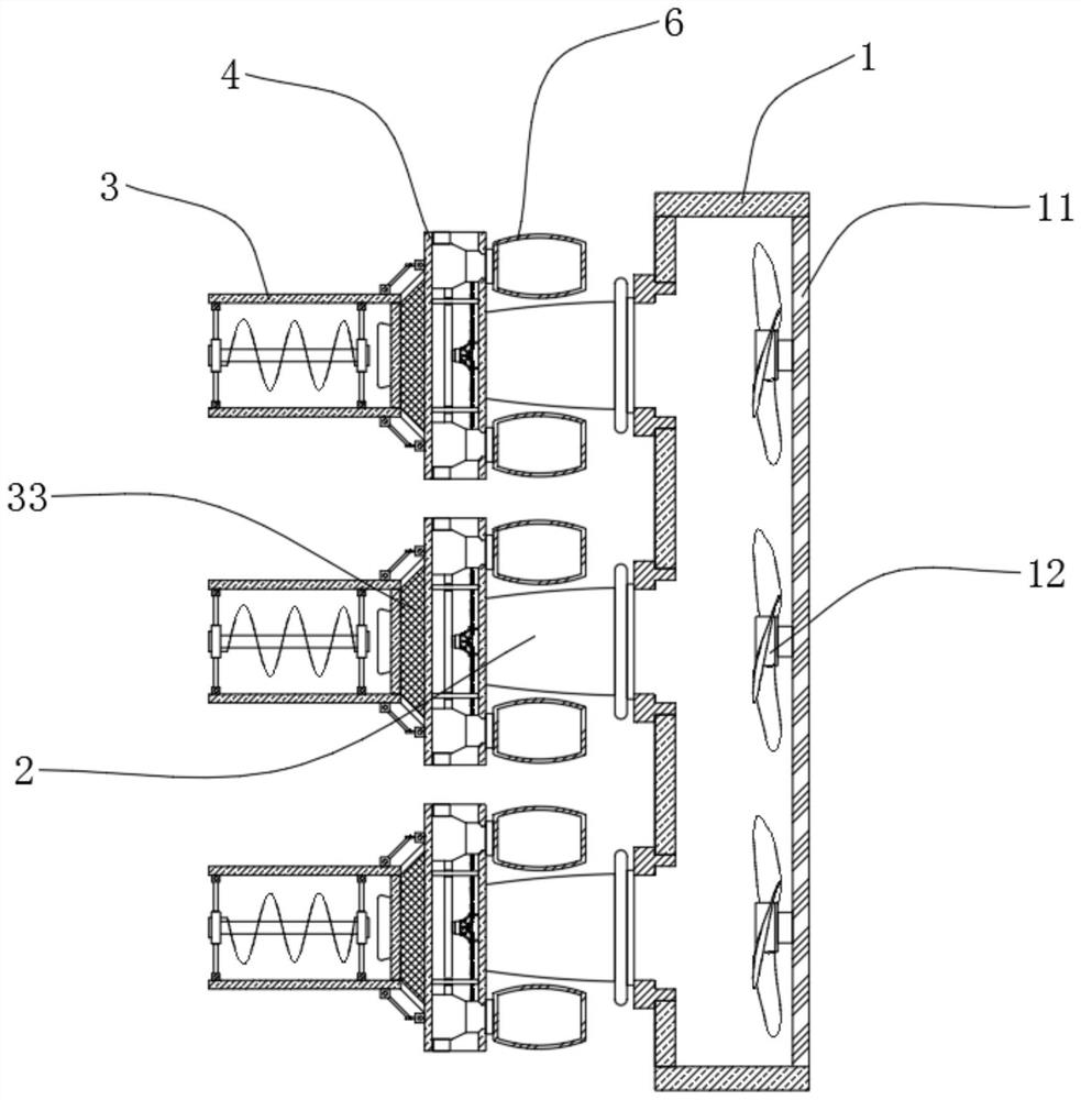
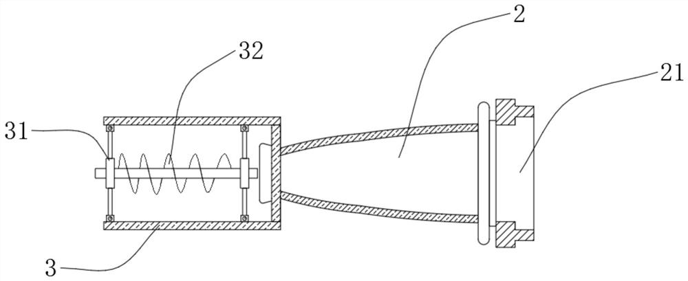
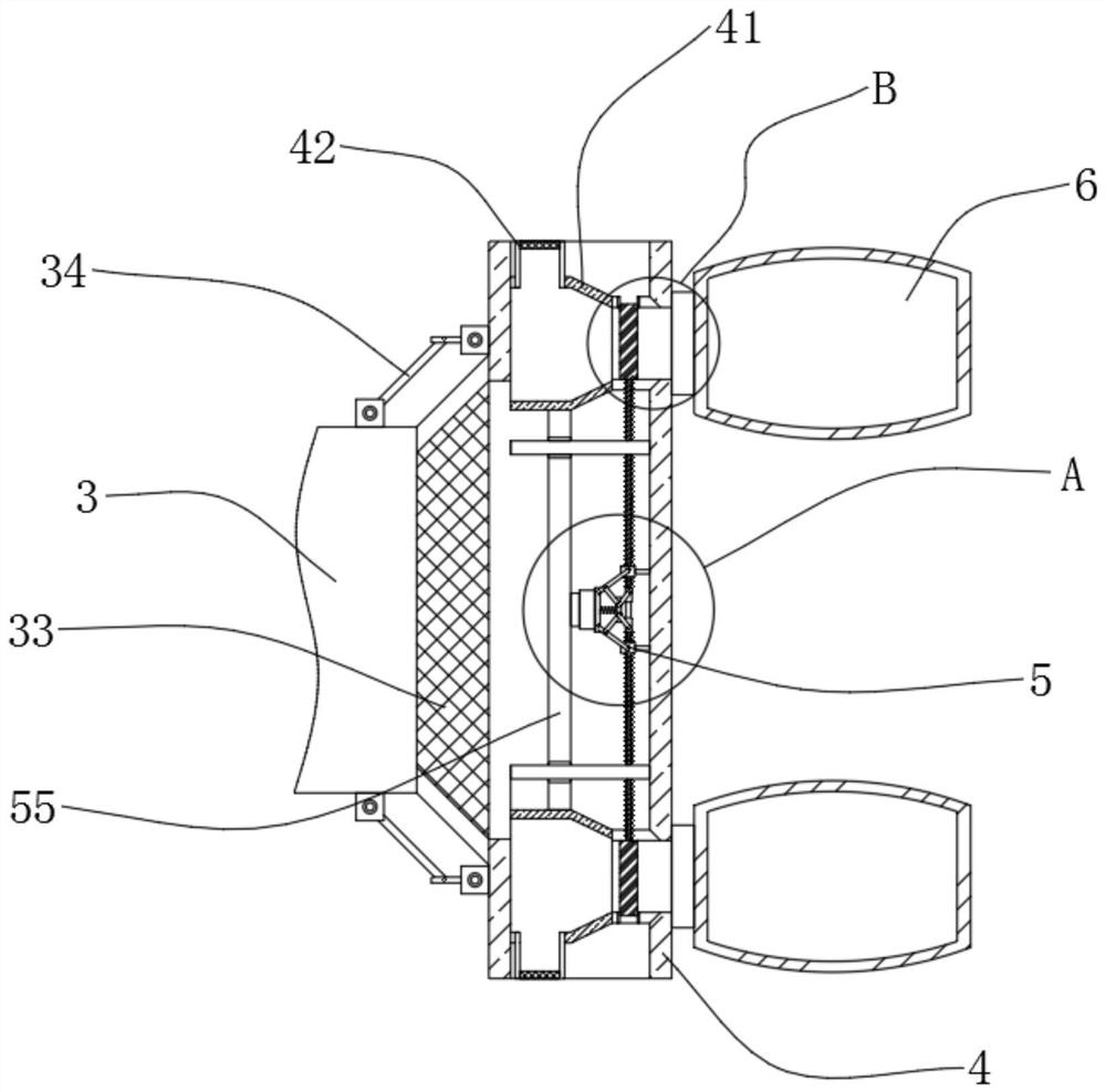
[0026] see Figure 1-5 , a computer radiator utilizing cyclone centrifugal separation, comprising an air inlet 1, one side of the air inlet 1 is fixedly connected with an air inlet grid 11, one side of the air inlet grid 11 is rotatably connected with a fan blade 12, and The wind grid 11 is connected with the heat dissipation fins, so that the airflow generated in the air inlet 1 directly enters the heat dissipation fins to dissipate heat. At the same time, th...


PUM


Abstract

The invention belongs to the technical field of computer hardware, and discloses a computer radiator utilizing cyclone centrifugal separation. The computer radiator comprises an air inflow device; oneside of the air inflow device is fixedly connected with an air inflow pipe; one side of the air inflow pipe is fixedly connected with a cyclone separation pipe; the inner side wall of the cyclone separation pipe is fixedly connected with a and frame; a spiral blade is fixedly connected to the interior of the supporting frame; a dust collection cover is fixedly connected to the side, close to theair inflow pipe, of the cyclone separation pipe; a centrifugal force generated by the dust is larger than that generated by the air, so that the dust is thrown to the outer side of the cyclone separation pipe, the air enters the air inflow pipe, the purpose of separating the dust is achieved, the purified air directly enters the air inflow device and then passes through cooling fins, and thereforethe air is effectively prevented from directly passing through the cooling fins, therefore, the dust in the air will not be attached to the surfaces of the radiating fins, the service life of the radiator is effectively prolonged, and radiating efficiency of the radiator is effectively improved.

Description

technical field [0001] The invention relates to the technical field of computer hardware, in particular to a computer radiator utilizing cyclone centrifugal separation. Background technique [0002] A computer, commonly known as a computer, is a modern electronic computing machine used for high-speed computing. It can perform numerical calculations, logical calculations, and has storage and memory functions. It is a modern intelligent electronic device that can run according to the program and process massive data automatically and at high speed. Among them, the computer is composed of a hardware system and a software system. In the hardware system, the CPU is the most important hardware in the system. During the use of the CPU, A radiator is usually required to dissipate the heat generated during its work. [0003] In the prior art, the radiator is usually composed of a heat dissipation fan and heat dissipation fins. During the working process of the heat dissipation fan, ...

Claims


Application Information

Patent Timeline
Patent Type & Authority Applications(China)
IPC IPC(8): G06F1/20F04D25/16F04D29/70
CPCF04D25/166F04D29/703G06F1/20
Inventor 尚雁
Owner 杭州郜灵科技有限公司
Learn More