Comprehensive energy system demand response method based on dynamic process optimization

An integrated energy system, demand response technology, applied in information technology support systems, resources, data processing applications, etc., can solve problems such as not considering energy consumption

Pending Publication Date: 2020-12-04
STATE GRID JIANGSU ELECTRIC POWER CO LTD MARKETING SERVICE CENT +5
0 Cites 0 Cited by

AI-Extracted Technical Summary

Problems solved by technology

However, these studies did not consider energy consumption
Furthermore, undoubtedly one of the most challenging aspects...

Method used

The comprehensive energy system demand response method based on dynamic process optimization designed by the above-mentioned technical solution is based on a new design framework, with electricity charges as the main line factor, introducing electricity purchase costs during the production of power plants, and corresponding transitions between different power generation operation modes The three factors of cost and energy storage unit inventory cost are jointly involved in the application, and the power supply objective function is constructed to provide p...

Abstract

The invention relates to a comprehensive energy system demand response method based on dynamic process optimization, which is based on a brand-new design architecture, takes electric charge as a mainfactor, introduces three factors of power purchase cost in the production period of a power plant, transition cost corresponding to transition between different power generation operation modes and inventory cost of an energy storage unit, and jointly participates in application. A power supply objective function is constructed, and more efficient power supply scheme selection is provided for a power plant; the design method has the characteristics of comprehensiveness, independence, easy measurement, flexibility and practicability, required data sources are convenient and easy to understand,and meanwhile, due to the fact that the proposed optimization formula is easier to process and a pre-calculated transition curve is used, the non-convexity of the basic optimization formula can be reduced, and the reliability of the design method is improved. The optimization problem can be solved more easily, and the response efficiency of the actual work of the power plant is improved.

Application Domain

ForecastingResources +1

Technology Topic

Optimization problemDemand response +12

Image

  • Comprehensive energy system demand response method based on dynamic process optimization
  • Comprehensive energy system demand response method based on dynamic process optimization
  • Comprehensive energy system demand response method based on dynamic process optimization

Examples

  • Experimental program(1)

Example Embodiment

[0049] The specific implementation manners of the present invention will be further described in detail below in conjunction with the accompanying drawings.
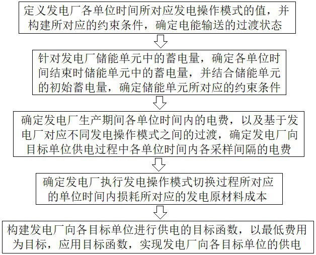
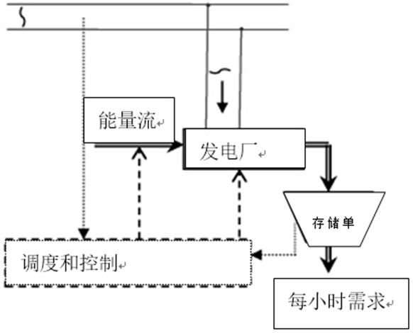
[0050] The present invention designs an integrated energy system demand response method based on dynamic process optimization, such as figure 2 As shown, it is used for the power plant with energy storage unit to realize the optimal power supply of the power plant to each target unit. In practical applications, such as figure 1 As shown, the following steps A to E are specifically performed.
[0051] Step A. Based on the different power generation operation modes adopted by the power plant according to different users, different natural conditions, and national regulation and control requirements within a certain period of time, for each power generation operation mode m corresponding to the power plant, m∈M, M Indicates the number of power generation operation modes corresponding to the power plant, and defines the value of the power generation operation mode m corresponding to each unit time h of the power plant as and build The corresponding constraint conditions, and determine the transition state of electric energy transmission, and then enter step B.
[0052] In practical applications, the above step A specifically performs the following steps A1 to A2.
[0053] Step A1. For each power generation operation mode m corresponding to the power plant, m∈M, M represents the number of power generation operation modes corresponding to the power plant, and the value of the power generation operation mode m corresponding to each unit time h of the power plant is defined as and build The corresponding constraints are as follows:
[0054]
[0055]
[0056]
[0057] in, Indicates the value of the power generation operation mode m corresponding to the initial time of the power plant, If the power generation operation mode m corresponding to each unit time h of the power plant is lower than the rated power generation level, then If the power generation operation mode m corresponding to each unit time h of the power plant is higher than the rated power generation level, then If the power generation operation mode m corresponding to each unit time h of the power plant is equal to the rated power generation level, then Equation (1) indicates that in each unit time h, the power plant can only have one power generation operation mode; Equation (2) indicates that when the power generation operation mode remains unchanged, as time changes, The value remains unchanged; Equation (3) means that the assign the value to Then go to step A2.
[0058] Step A2. Indicates whether the power plant is in the transition phase of the power generation operation mode, if the power plant is in the transition phase of the power generation operation mode, that is From unit time h-1 to unit time h, the power plant is in the transition stage from power generation operation mode m to power generation operation mode m', then If the power plant is not in the transition phase of the generating mode of operation, then The transition state of the electrical energy supply is thus determined.
[0059] Step B. Aiming at the storage capacity in the energy storage unit of the power plant, determine the storage capacity s in the energy storage unit at the end of each unit time h h , combined with the initial storage capacity s of the energy storage unit 0 , determine the constraints corresponding to the energy storage unit, and then enter step C.
[0060] The energy storage unit of the power plant is composed of power storage devices and is powered by the power plant, which can meet the minimum hourly demand d on the demand side h. Likewise, similar to the backward binary variable defined in equation (2), s h is the storage capacity in the energy storage unit at the end of each unit time h, is the initial storage capacity of each unit time h of the energy storage unit of the power plant, as shown below:
[0061]
[0062]
[0063] First, the initial storage capacity s 0 At time h=1 assigned to (For example, at the end of the previous time period, the energy storage is 3, then the initial energy storage of the next time period is 3, and then use the following formula to calculate the energy storage of the next time period, after the end is 4, then the next time period The initial energy storage of the stage is 4. And so on.)
[0064] The implementation of the above step B in practical applications is accomplished by performing the following steps B1 to B2.
[0065] Step B1. According to the minimum power demand d of each unit time h of each target unit as a whole h , and the initial storage capacity of each unit time h of the energy storage unit of the power plant According to the following formula:
[0066]
[0067] Determine the storage capacity s in the energy storage unit at the end of each unit time h h , where p m Indicates the power production level of the power plant corresponding to the power generation operation mode m, t m′,m Indicate the transition time from the power generation operation mode m corresponding to the power plant to the power generation operation mode m', and then enter step B2.
[0068] Step B2. Combine s h Constraints satisfied 0≤s h ≤s max ,s max Indicates the maximum storage capacity in the energy storage unit at the end of each unit time h, and obtains the storage capacity s in the energy storage unit at the end of the last unit time H of the power supply of the power plant H Satisfy the following constraints:
[0069] the s H ≥s 0 (10)
[0070] That is, constituting the constraints corresponding to the energy storage unit.
[0071] In addition, we consider the consumption of electricity bills. The power consumption can be divided into two parts: one part is related to the production time period, and the other part is related to the transition time period. The production time period is the power generation process of the power plant, and the transition time period is the electricity from A dynamic process of transmission from power plants to users. That is, the following step C is performed.
[0072] Step C. Determine the electricity cost ΔE for each unit time h during the production period of the power plant h , and based on the transition between different power generation operation modes corresponding to the power plant, determine the electricity cost of each sampling interval i in each unit time h in the process of power supply from the power plant to the target unit where i=1,...,N m′,m , N m′,m Indicates the number of sampling points during the transition from the power generation operation mode m' corresponding to the power plant to the power generation operation mode m, and then enters step D.
[0073] In a specific application, the above step C realizes the execution of the scheme designed in step C through the execution of the following steps C1 to C2.
[0074] Step C1. According to the following formula:
[0075]
[0076] Determine the electricity cost ΔE within each unit time h during the production of the power plant h , where a represents the ratio of required energy to material flow rate, 1 to n representing the energy storage unit and each target unit respectively correspond to the steady-state value of the power generation operation mode m, n represents the sum of the number of target units and the number of energy storage units, and then enter step C2.
[0077] Step C2. N in the transition process based on the power generation operation mode m' corresponding to the power plant to the power generation operation mode m m′,m sampling points according to the following formula:
[0078]
[0079] Determine the electricity cost of each sampling interval i in each unit time h in the process of the power plant supplying power to the target unit 1 to n representing the energy storage unit and each target unit are based on the power consumption sampling values ​​corresponding to each sampling interval i during the transition process from the power plant corresponding to the power generation operation mode m' to the power generation operation mode m, and Δt represents the duration of the sampling interval.
[0080] The extra excessive cost means that there will be losses during the transition period, which will be converted into electricity charges. During the transition period, there will be a certain waste of resources due to the switching of the operation mode, that is, step D is performed next.
[0081] Step D. According to the following formula:
[0082]
[0083] Obtain the cost of raw materials for power generation corresponding to the loss per unit time h corresponding to the switching process of the power generation operation mode in the power plant in, Indicate the unit price of the power generation raw material cost of the power plant, and then enter step E.
[0084] Step E. Construct the objective function for the power plant to supply power to each target unit, aim at the lowest cost, apply the objective function, and realize the power supply from the power plant to each target unit.
[0085] Specifically, in step E, in practical application, the following steps E1 to E2 are performed.
[0086] Step E1. Construct the objective function of the power plant to supply power to each target unit as follows:
[0087] J=min{Φ 1 +Φ 2 +Φ 3} (14)
[0088]
[0089]
[0090]
[0091] Among them, Φ 1 Indicates the power purchase cost of the power plant corresponding to the production period, Φ 2 Indicates the transition cost of the power plant corresponding to the transition between different power generation operation modes, Φ 3 Indicates the inventory cost of energy storage units in the power plant; Indicates the electricity price that changes in real time, Indicates the unit inventory cost electricity of the energy storage unit of the power plant; then enter step E2.
[0092] In practical applications, in the above objective function, since the energy supply changes with the change of the demand side, ΔE h is a variable, as the power generation level changes, the state also changes accordingly, so is also a variable, electricity price It changes every hour, and the electricity selling price is proportional to the current electricity price, the ratio is η, s h It is the minimum storage capacity of the energy storage device, and generally does not change much.
[0093] Step E2. Taking the lowest cost as the goal, apply the objective function to realize the power supply from the power plant to each target unit.
[0094] The above-mentioned technical solution is designed based on the dynamic process optimization integrated energy system demand response method, based on the new design framework, taking the electricity cost as the main line factor, introducing the power purchase cost during the production period of the power plant, the transition cost corresponding to the transition between different power generation operation modes, and storage The tripartite factors of energy unit inventory cost, participate in the application together, construct the power supply objective function, and provide more efficient power supply scheme selection for power plants; the designed method has the characteristics of comprehensiveness, independence, ease of measurement, flexibility and practicability. Moreover, the source of required data is convenient and easy to understand. At the same time, because the proposed optimization formula is easier to handle, the use of pre-calculated transition curves can reduce the non-convexity of the underlying optimization formula, and the resulting optimization problems can be solved more easily , to improve the response efficiency of the actual work of the power plant.
[0095] The embodiments of the present invention have been described in detail above in conjunction with the accompanying drawings, but the present invention is not limited to the above embodiments, and can also be made without departing from the gist of the present invention within the scope of knowledge possessed by those of ordinary skill in the art. Variations.

PUM

no PUM

Description & Claims & Application Information

We can also present the details of the Description, Claims and Application information to help users get a comprehensive understanding of the technical details of the patent, such as background art, summary of invention, brief description of drawings, description of embodiments, and other original content. On the other hand, users can also determine the specific scope of protection of the technology through the list of claims; as well as understand the changes in the life cycle of the technology with the presentation of the patent timeline. Login to view more.
Why Eureka
Try Eureka