
Manufacturing method of display substrate, display substrate, display panel and display device

A manufacturing method and technology for display substrates, which are applied in semiconductor/solid-state device manufacturing, electrical components, electrical solid-state devices, etc.

Active Publication Date: 2020-12-04
HEFEI XINSHENG OPTOELECTRONICS TECH CO LTD +1
View PDF5 Cites 2 Cited by
  • Summary
  • Abstract
  • Description
  • Claims
  • Application Information

AI Technical Summary

Problems solved by technology

However, since the large-size OLED is an Open Mask (open mask), the entire AA area (display area) will be covered by the EL material (luminescent material), how to penetrate the EL, and then realize the connection between the cathode and the auxiliary cathode is the responsibility of the auxiliary cathode. main difficulty

Method used


Image

  • Manufacturing method of display substrate, display substrate, display panel and display device
  • Manufacturing method of display substrate, display substrate, display panel and display device
  • Manufacturing method of display substrate, display substrate, display panel and display device

Examples


Embodiment Construction

[0038] Example embodiments will now be described more fully with reference to the accompanying drawings. Example embodiments may, however, be embodied in many forms and should not be construed as limited to the examples set forth herein; rather, these embodiments are provided so that this disclosure will be thorough and complete and will fully convey the concept of example embodiments to those skilled in the art. The described features, structures, or characteristics may be combined in any suitable manner in one or more embodiments. In the following description, numerous specific details are provided in order to give a thorough understanding of embodiments of the present disclosure. However, those skilled in the art will appreciate that the technical solutions of the present disclosure may be practiced without one or more of the specific details being omitted, or other methods, components, devices, steps, etc. may be adopted. In other instances, well-known technical solution...


PUM


Abstract

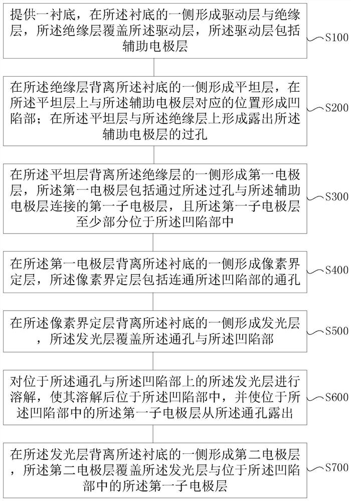
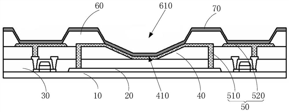
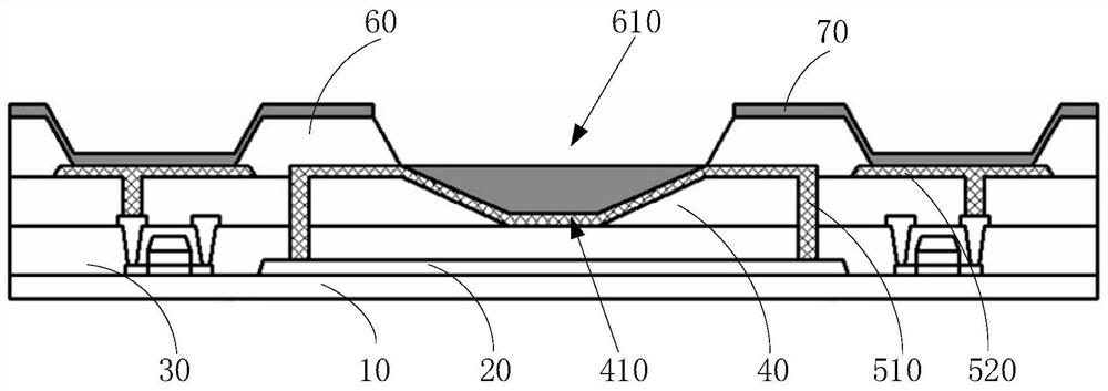
The invention relates to a manufacturing method of a display substrate, the display substrate, a display panel and a display device. The manufacturing method comprises the steps that a driving layer comprising an auxiliary electrode layer and an insulating layer covering the driving layer are formed on one side of a substrate; a flat layer is formed on the side, deviating from the substrate, of the insulating layer, and a concave part is formed in the position, corresponding to the auxiliary electrode layer, of the flat layer; via holes for exposing the auxiliary electrode layer are formed onthe flat layer and the insulating layer; a first electrode layer is formed on one side, deviating from the insulating layer, of the flat layer, wherein the first electrode layer comprises a first sub-electrode layer which is connected with the auxiliary electrode layer and at least partially located in the concave part; a pixel defining layer comprising a through hole communicated with the concavepart is formed on one side, deviating from the substrate, of the first electrode layer; a light-emitting layer is formed on one side, deviating from the substrate, of the pixel defining layer, wherein the light-emitting layer covers the through hole and the concave part; and the light-emitting layer on the through hole and the concave part is dissolved, the dissolved light-emitting layer is located in the concave part, and the first sub-electrode layer located in the concave part is exposed out of the through hole.

Description

technical field [0001] The present disclosure relates to the field of display technology, in particular, to a method for manufacturing a display substrate, a display substrate, a display panel, and a display device. Background technique [0002] OLED (Organic Light-Emitting Diode) is a thin-film light-emitting device made of organic semiconductor materials, which has the characteristic of self-luminescence. Top emission is one of the large-size OLED panel structures, which has a large aperture ratio, which can effectively increase the lifespan and improve the picture quality. Top emission requires the cathode to have a matched work function, high transmittance and low resistivity. Because the work function affects optical parameters such as luminous efficiency, since the light emitted from the top needs to be transmitted from the cathode, a higher transmittance is an inevitable requirement, and the size of the resistivity determines the uniformity of the voltage. If the res...

Claims


Application Information

Patent Timeline
Patent Type & Authority Applications(China)
IPC IPC(8): H01L51/56H01L51/52H01L27/32
CPCH10K59/122H10K50/82H10K50/824H10K71/00
Inventor 胡友元栾梦雨吴新风韩君奇王欣竹
Owner HEFEI XINSHENG OPTOELECTRONICS TECH CO LTD
Learn More