Power distribution cabinet with automatic cooling function

A technology for automatic cooling and power distribution cabinets, applied in substation/power distribution device shells, electrical components, substation/switch layout details, etc., can solve problems such as lack of circuit control, poor heat dissipation efficiency, fire loss, etc., to achieve Improve the uniformity of heat dissipation, increase the contact area, and facilitate the effect of heat dissipation

Inactive Publication Date: 2020-12-04
湖北天晟一林科技有限公司
View PDF10 Cites 0 Cited by
  • Summary
  • Abstract
  • Description
  • Claims
  • Application Information

AI Technical Summary

Problems solved by technology

[0005] In order to solve the above technical problems, the present invention provides a power distribution cabinet with an automatic cooling function to solve the problem that when the power distribution cabinet in the above patent is in use, the heat dissipation efficiency is not good, and the internal components of the power distribution cabinet are easily caused by overheating. Ineffective, can not play the role of circuit control, and even easily cause the wire to burn, causing fire and causing greater losses

Method used


Image

  • Power distribution cabinet with automatic cooling function
  • Power distribution cabinet with automatic cooling function
  • Power distribution cabinet with automatic cooling function

Examples


Embodiment

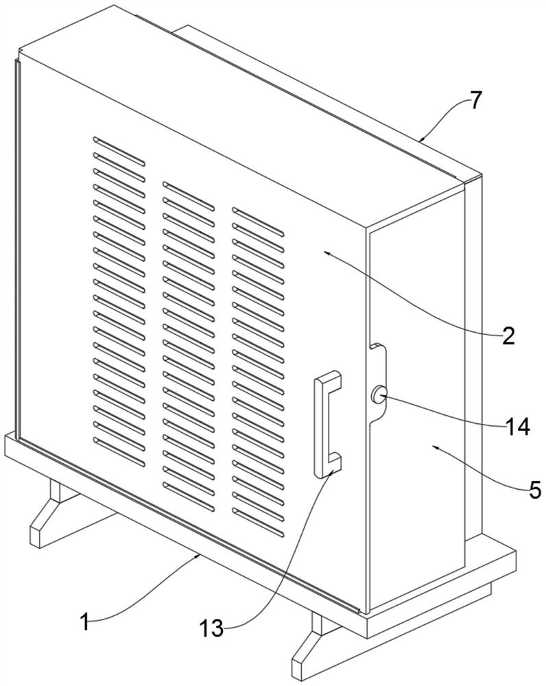
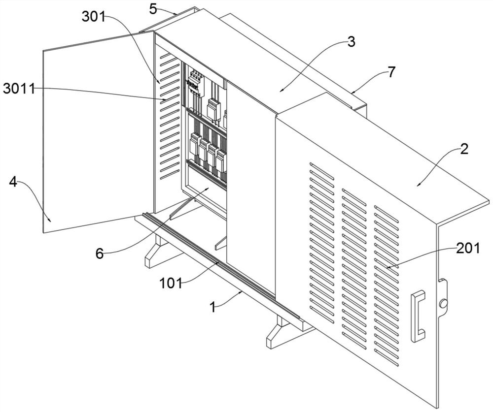
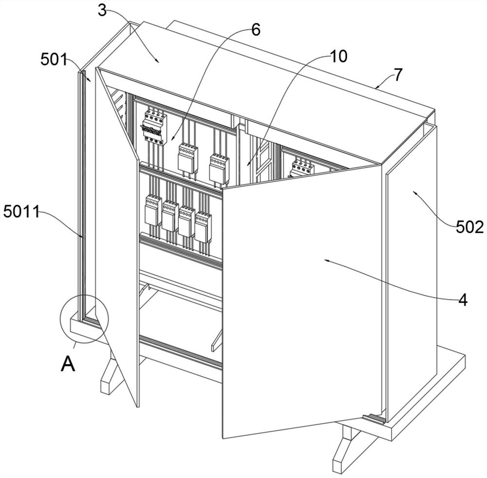
[0034] as attached figure 1 To attach Figure 9 Shown:

[0035] The present invention provides a power distribution cabinet with automatic cooling function, which includes a front shield 2, an inner cabinet body 3, an inner box door 4, a side windshield 5, a switchboard 6, a rear baffle 7, a control panel 8, Distributor frame 10, driver 11, heat dissipation fan 12, handle 13; the bottom of inner cabinet body 3 is fixedly connected to the top of underframe 1, and a lower guide rail 101 is fixedly connected to the front edge of the upper surface of underframe 1, and lower guide rail 101 , the chassis 1 of this structure is as Figure 9As shown, the lower guide rail 101 facilitates the movement of the front shield 2 on the chassis 1, and facilitates the disassembly and fixing of the front shield 2; the front shield 2 is slidably connected on the upper surface of the chassis 1; the inner box door 4 is hinged Rotationally connected to both sides of the front of the inner cabinet...


PUM


Abstract

The invention provides a power distribution cabinet with an automatic cooling function. The power distribution cabinet comprises a front shield, an inner cabinet body, an inner box door, a side wind shield, a distribution board, a rear baffle, a control panel, a shunt frame, a driving part, a cooling fan and a handle, wherein the lower portion of the inner cabinet body is fixedly connected to theupper portion of the bottom frame; the front shield is connected to the upper surface of the bottom frame in a sliding manner; the inner box doors are rotatably connected to two sides of the front part of the inner cabinet body through hinges; the side wind shield is divided into a left side plate and a right side plate which are respectively connected to two sides of the inner cabinet body through welding; the switchboard is fixedly connected to the inner side of the inner cabinet body through bolts; the rear baffle plate is connected to the rear surface of the inner cabinet body through welding; and the control panel is fixedly connected to the interior of the inner cabinet body. Therefore, the power distribution cabinet of the structure facilitates gas circulation, increases the contactarea of gas and the power distribution cabinet, is more beneficial to heat dissipation, improves the heat dissipation efficiency and heat dissipation uniformity, and solves the problems that an existing power distribution cabinet lacks a shell heat dissipation structure and is uneven in heat dissipation.

Description

technical field [0001] The invention belongs to the technical field of power distribution cabinets, and more specifically relates to a power distribution cabinet with an automatic cooling function. Background technique [0002] Power distribution cabinets are divided into power distribution cabinets, lighting distribution cabinets, and metering cabinets, and are the final equipment of the power distribution system. The power distribution cabinet is a general term for the motor control center. The power distribution cabinet is used in the occasions where the load is relatively scattered and there are few circuits; the motor control center is used in the occasions where the load is concentrated and there are many circuits. They distribute the electric energy of a certain circuit of the upper-level power distribution equipment to the nearest load. This level of equipment should provide protection, monitoring and control for the load. According to the requirements of electrica...

Claims


Application Information

Patent Timeline
Patent Type & Authority Applications(China)
IPC IPC(8): H02B1/30H02B1/56
CPCH02B1/30H02B1/565
Inventor 张诗逸
Owner 湖北天晟一林科技有限公司
Why Eureka
Try Eureka