Air conditioner emergency ventilation power supply circuit system
A technology for power supply circuits and air conditioners, which is used in control/regulation systems, emergency protection circuit devices, and wind power generation. Effect
- Summary
- Abstract
- Description
- Claims
- Application Information
AI Technical Summary
Problems solved by technology
Method used
Image
Examples
Embodiment 1
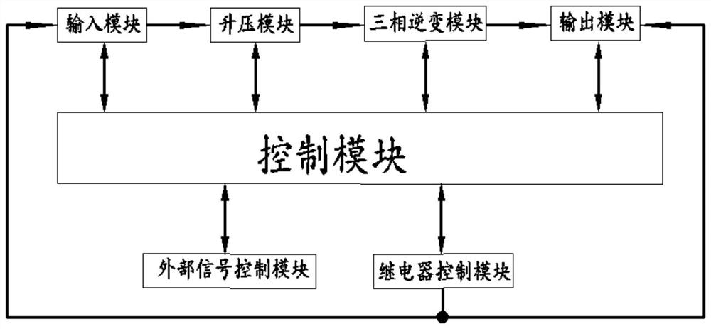
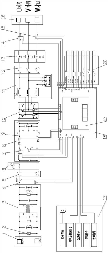
[0041]An air-conditioning emergency ventilation power supply circuit system, comprising a control module, an input module, an output module and a boost module 8, the control module including a DSP micro-control board 19 and an I / O driver board 18, and the I / O driver board 18 Pins are arranged on the pin, and the pins are connected with sensors, and the sensors include a first current sensor 7, a second current sensor 14, a third current sensor 15, a first voltage sensor 4 and a second voltage sensor 9, and the The first current sensor 7 and the second voltage sensor 9 are respectively connected to the boost module 8, the second current sensor 14 and the third current sensor 15 are respectively connected to the output module, and the first voltage sensor 4 is connected to the input module.
[0042] Adopt above-mentioned scheme, when input module, output module or step-up module break down in the air-conditioning emergency ventilation power supply circuit, the signal transmitted ...
Embodiment 2
[0062] The technical solution of this embodiment is basically the same as that of Embodiment 1, the difference is that:
[0063] In this embodiment, the specified range of the output voltage is DC 77-137.5V. Since the output voltage of the battery 1 is unstable and exceeds this threshold, an input overvoltage or undervoltage fault occurs, and the fault time exceeds the specified time. The module will cut off the input isolating switch 5 and the pre-charging control switch 601 in time according to the instructions of the control module, so as to keep the power supply isolated from the external input and output; The start command sent from the driver's cab will pull in the input isolating switch 5 and the output isolating switch 12. After the pre-charging process is completed, the pre-charging control switch 601 will be pulled in. So far, the input module is started.
Embodiment 3
[0065] This embodiment is basically the same as the above-mentioned technical solution, the difference is that:
[0066] In this embodiment, when the control module receives the emergency ventilation power start command sent by the driver's cab, it will first conduct a self-check on the feedback status of each internal module. If there is no abnormality, first confirm the current voltage range of the input module. If it meets the network voltage requirements DC 77-137.5V, then drive the input isolating switch 5 and the output isolating switch 12 to close, open the input and output channels, the battery 1 starts to charge the capacitor 803 of the boost module through the charging resistor 602, after the charging is completed, the control module is closed The pre-charge control switch 601 starts to send PWM waves to the power transistor 804 . The boost module 8 boosts the input voltage to a threshold voltage of DC 580V, and the DSP micro-control board 19 realizes the boost throu...
PUM
 Abstract
Description
Claims
Application Information
 - R&D
- Intellectual Property
- Life Sciences
- Materials
- Tech Scout
- Unparalleled Data Quality
- Higher Quality Content
- 60% Fewer Hallucinations
Browse by: Latest US Patents, China's latest patents, Technical Efficacy Thesaurus, Application Domain, Technology Topic, Popular Technical Reports.
© 2025 PatSnap. All rights reserved.Legal|Privacy policy|Modern Slavery Act Transparency Statement|Sitemap|About US| Contact US: help@patsnap.com


