
Machine for changing garden wastes into fertilizer
A garden waste and feeder technology, which is applied in the treatment of bio-organic parts, organic fertilizers, grains, etc., can solve the problems of garden waste consuming a lot of manpower and material resources, unsuitable for modern production and life, and physical discomfort.
- Summary
- Abstract
- Description
- Claims
- Application Information
AI Technical Summary
Problems solved by technology
Method used
Image

Examples
specific Embodiment approach 1
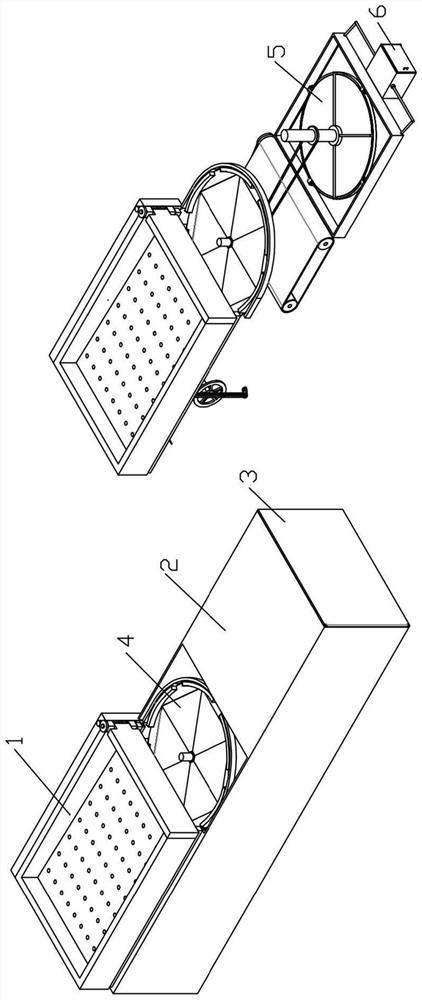
[0030] Combine below Figure 1-11 In order to solve the above-mentioned technical problems, the present invention relates to the technical field of garden machinery, more specifically, a garden waste chemical machine, comprising a screening device 1, a housing 2, a retrieving door 3, a centrifugal device 4, a crushing device 5 and Fermentation box 6; it is characterized in that: the sieving device 1 is movably connected with the housing 2, the housing 2 is hinged with the retrieving door 3, the housing 2 is provided with a centrifugal device 4, and the centrifugal device 4 A crushing device 5 is provided at the corresponding position of the lower end of the container, and the crushing device 5 is connected with the fermentation box 6; the garden waste is poured into the sieving device 1, and the sieving device 1 screens out sand and stone particles in the waste , then the unremovable sand and stone particles are removed by centrifugal force through the centrifugal device 4, an...
specific Embodiment approach 2
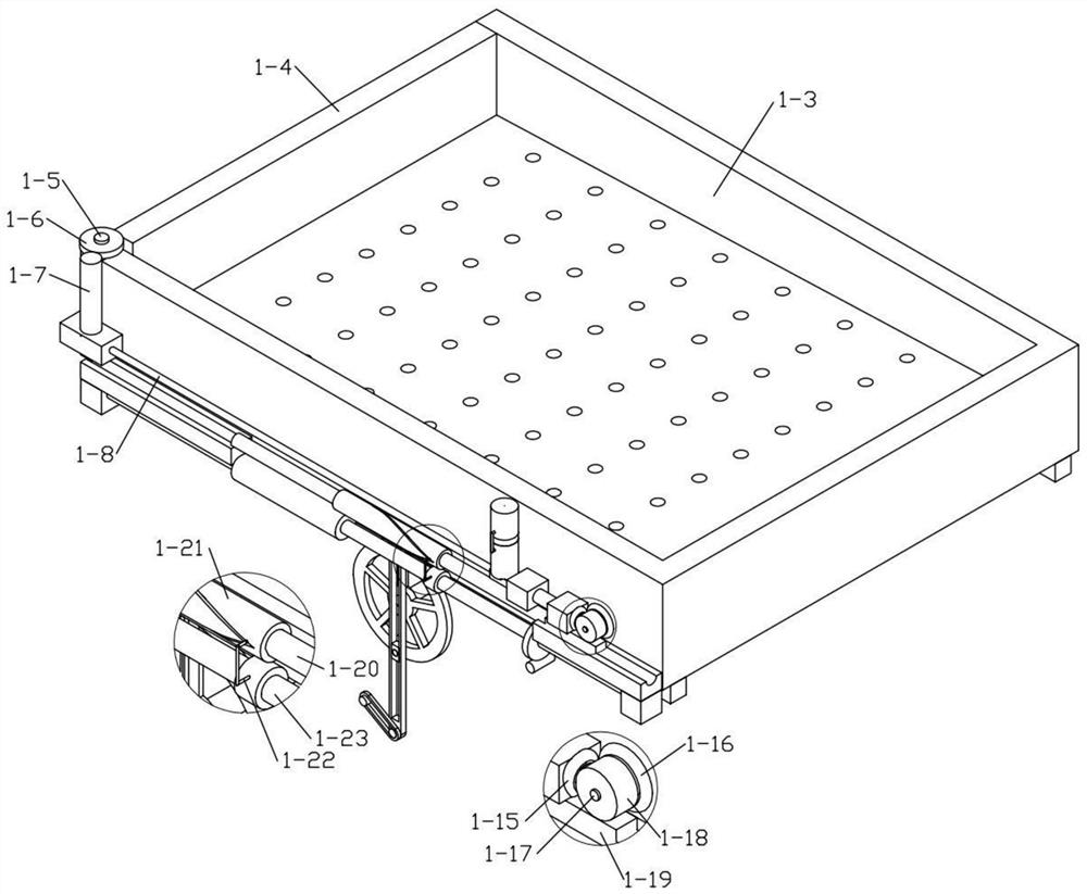
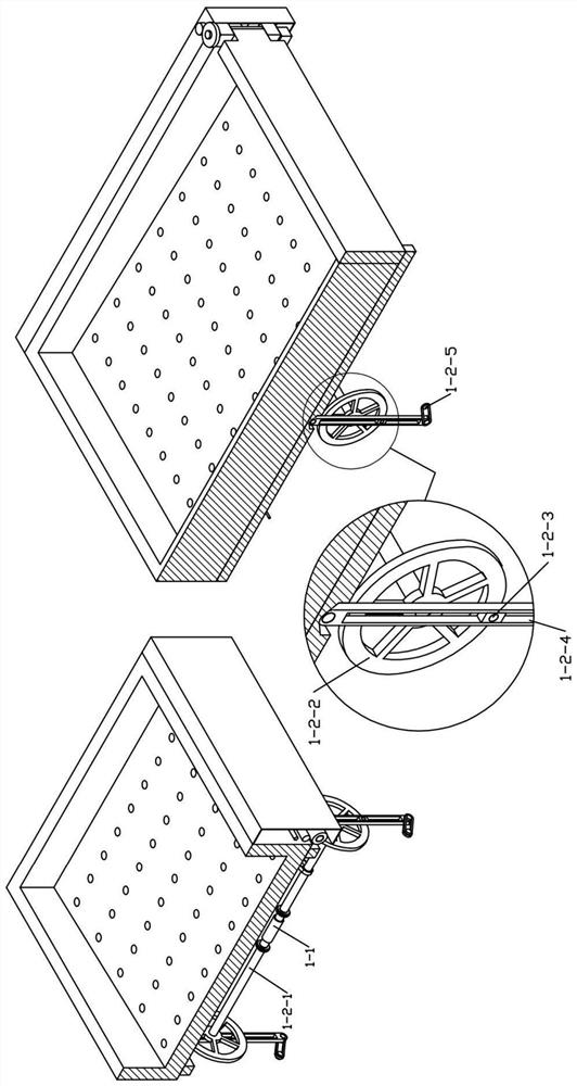
[0032] Combine below Figure 1-11 Describe this embodiment, this embodiment will further explain the first embodiment, the sieving device 1 includes a sieving motor 1-1, a transmission device 1-2, a sieve body 1-3, a discharge door 1-4, a hinge shaft 1-5, the first discharge turbine 1-6, the first discharge worm 1-7, the first discharge screw 1-8, the first screw nut 1-9, the first discharge helical gear 1-10 , the second discharge helical gear 1-11, the first discharge shaft 1-12, the second discharge turbine 1-13, the second discharge shaft 1-14, the third discharge helical gear 1-15, the fourth Discharge helical gear 1-16, third discharge shaft 1-17, discharge transmission gear 1-18, discharge transmission rack 1-19, third discharge worm 1-20, reversing roller 1-21, Reversing lever 1-22, fourth discharge shaft 1-23, third discharge worm gear 1-24, fourth discharge worm 1-25, fifth discharge shaft 1-26, first discharge pulley 1 -27. The second discharge pulley 1-28 and the...
specific Embodiment approach 3
[0037] Combine below Figure 1-11 Describe this embodiment, this embodiment will further explain Embodiment 1, the centrifugal device 4 includes a transmission shaft 4-1, a first transmission pulley 4-2, a first transmission belt 4-3, a second transmission pulley 4-4, The second transmission belt 4-5, the transmission disc 4-6, the first transmission rod 4-7, the second transmission rod 4-8, the fixed rod 4-9, the fixed rack 4-10, the fixed gear 4-11, the fixed Shaft 4-12, first centrifugal pulley 4-13, second centrifugal pulley 4-14, centrifugal belt 4-15, centrifugal shaft 4-16, first centrifugal helical gear 4-17, second centrifugal helical gear 4 -18, centrifugal screw 4-19, centrifugal screw nut 4-20, first articulated rod 4-21, second articulated rod 4-22, third articulated rod 4-23, centrifugal frame 4-24, anti-out material semicircular frame 4-25 and hinged plate 4-26; two groups of transmission shafts 4-1 are arranged in the housing 2, and the first transmission pull...
PUM
 Abstract
Description
Claims
Application Information