Copper part forging equipment and method

A technology for copper parts and equipment, which is applied to the forging equipment of copper parts and its forging field, can solve the problems of the drop of punch yield strength, the inability to directly forge the inner hole structure, and the difficulty in controlling the effective spraying amount.

Active Publication Date: 2020-12-08
ZHEJIANG ANDEKAI FLUID EQUIP TECH CO LTD
View PDF9 Cites 3 Cited by
  • Summary
  • Abstract
  • Description
  • Claims
  • Application Information

AI Technical Summary

Problems solved by technology

[0002] When existing copper parts are used to forge boiler valves and other components, they are usually forged with a die forging hammer, which can forge the outer structure, but cannot directly forge the inner hole structure, which needs to be processed entirely by cutting and drilling. , leading to poor internal forgeability, which affects internal quality, and a large amount of waste will be generated in the inner hole, and the processing efficiency is low. Therefore, this design adopts a hot forging die structure that is directly punched during the forging process;
[0003] However, the working conditions of the hot forging die are very harsh. It has to withstand high temperature, high pressure, and severe friction caused by the violent flow of the hot metal blank on the surface of the mold cavity, which can easily lead to cracks, damage and thermal wear on the surface of the punch. The life of hot forging dies is low, and the forming quality is poor. Therefore, in order to prevent the

Method used


Image

  • Copper part forging equipment and method
  • Copper part forging equipment and method
  • Copper part forging equipment and method

Examples


Embodiment Construction

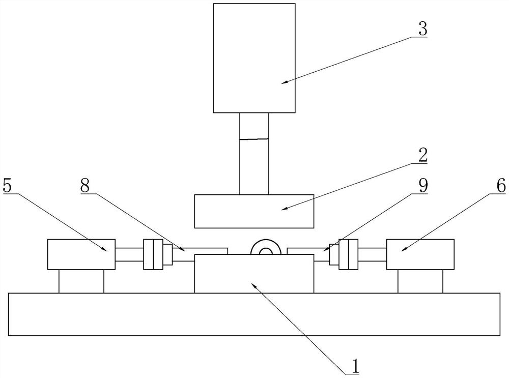
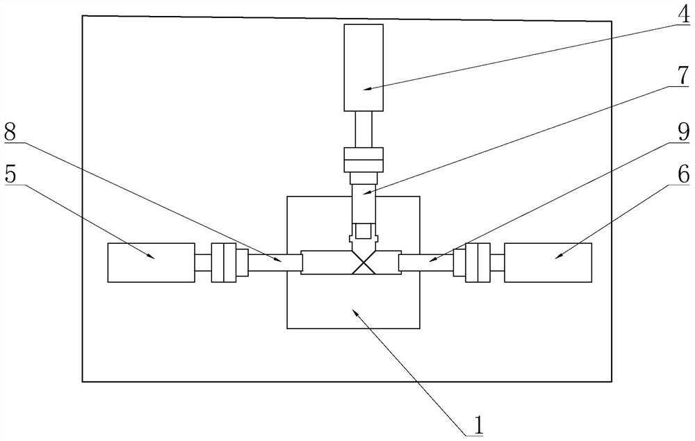
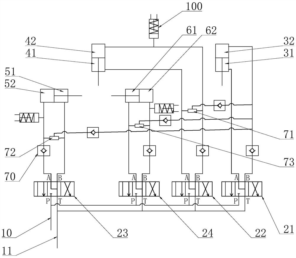
[0057] Below in conjunction with accompanying drawing, the present invention will be further described with specific embodiment, see Figure 1-6 :

[0058] A kind of forging equipment for copper parts, including multi-directional die forging hydraulic equipment and hydraulic drive system, said multi-directional die forging hydraulic equipment includes frame, lower die 1, upper die 2, top stamping cylinder 3, rear side stamping cylinder 4 , the left side stamping cylinder 5 and the right side stamping cylinder 6, a mold cavity is formed between the upper die 2 and the lower die 1, and the rear ejector pin 7, the left ejector pin 8 and the right ejector pin are also arranged between the upper die 2 and the lower die 1 The ejector pin 9, the lower mold 1 is fixed on the frame, the top stamping cylinder 3 is fixed on the frame and used to drive the lifting of the upper mold 2, the rear stamping cylinder 4 is fixed on the frame and used to drive the expansion and contraction of the...


PUM


Abstract

The invention discloses copper part forging equipment and method. The copper part forging equipment and method have the characteristics of high forging efficiency and good forming quality. The technical scheme is characterized in that the equipment comprises a multi-directional die forging hydraulic device and a hydraulic driving system; the multi-directional die forging hydraulic device comprisesa rack, a lower die, an upper die, a top stamping cylinder, a rear side stamping cylinder, a left side stamping cylinder and a right side stamping cylinder, a rear lifting pin, a left lifting pin anda right lifting pin are further arranged between the upper die and the lower die, the lower die is fixed to the rack, the top stamping cylinder is fixed to the rack and used for driving the upper dieto ascend and descend, the rear side stamping cylinder is fixed to the rack and used for driving the rear lifting pin to stretch out and draw back, the left side stamping cylinder is fixed to the rack and used for driving the left lifting pin to stretch out and draw back, and the right side stamping cylinder is fixed to the rack and used for driving the right lifting pin to stretch out and draw back; and the hydraulic driving system is used for controlling the operation states of the top stamping cylinder, the rear side stamping cylinder, the left side stamping cylinder and the right side stamping cylinder. The copper part forging equipment and method are applicable to the technical field of forging.

Description

technical field [0001] The invention belongs to the technical field of forging, in particular to forging equipment and a forging method for copper parts. Background technique [0002] When existing copper parts are used to forge boiler valves and other components, they are usually forged with a die forging hammer, which can forge the outer structure, but cannot directly forge the inner hole structure, which needs to be processed entirely by cutting and drilling. , leading to poor internal forgeability, which affects internal quality, and a large amount of waste will be generated in the inner hole, and the processing efficiency is low. Therefore, this design adopts a hot forging die structure that is directly punched during the forging process; [0003] However, the working conditions of the hot forging die are very harsh. It has to withstand high temperature, high pressure, and severe friction caused by the violent flow of the hot metal blank on the surface of the mold cavit...

Claims


Application Information

Patent Timeline
IPC IPC(8): B21J5/02B21J9/12B21J9/20B21J13/02B21D28/24
CPCB21D28/24B21J5/002B21J5/02B21J9/12B21J9/20B21J13/02
Inventor 查昭陈金勇陈礼宏
Owner ZHEJIANG ANDEKAI FLUID EQUIP TECH CO LTD
Why Eureka
Try Eureka