Intelligent adjustment charging station for new energy automobile

A new energy vehicle, intelligent adjustment technology, applied in the direction of electric vehicle charging technology, charging stations, electric vehicles, etc., can solve the problem that the photovoltaic panel structure is difficult to adjust flexibly, to avoid sun exposure, reduce the possibility, and reduce the occurrence of safety accidents Effect

Inactive Publication Date: 2020-12-08
徐蕊
View PDF0 Cites 3 Cited by
  • Summary
  • Abstract
  • Description
  • Claims
  • Application Information

AI Technical Summary

Problems solved by technology

[0005] The purpose of the present invention is to provide an intelligent adjustable charging station for new energy vehicles that can automatically adju

Method used


Image

  • Intelligent adjustment charging station for new energy automobile
  • Intelligent adjustment charging station for new energy automobile
  • Intelligent adjustment charging station for new energy automobile

Examples


Embodiment 1

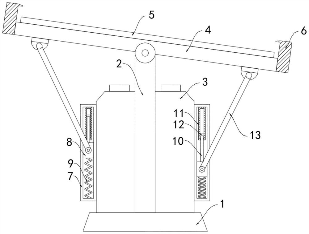
[0018] like figure 1 As shown, an intelligent adjustable charging station for new energy vehicles includes a base 1, a column 2 and a charging pile body 3, the lower end of the column 2 is fixedly connected to the upper surface of the base 1, and the upper end of the column 2 runs through the charging pile body 3 and is rotatably connected. There is a bearing plate 4 , a photovoltaic panel 5 is installed on the upper surface of the bearing plate 4 , and an enclosure 6 is fixedly connected to the side wall of the bearing plate 4 .

[0019] The sidewalls on both sides of the charging pile body 3 are fixedly connected with a limit sliding frame 7 extending in the vertical direction, and a sliding block 8 is slidably connected in the limit sliding frame 7, and the lower end of the sliding block 8 is connected to the limit by the support spring 9. The inner bottom surface of the sliding frame 7 is fixedly connected, the upper end of the sliding block 8 is fixedly connected with the...

Embodiment 2

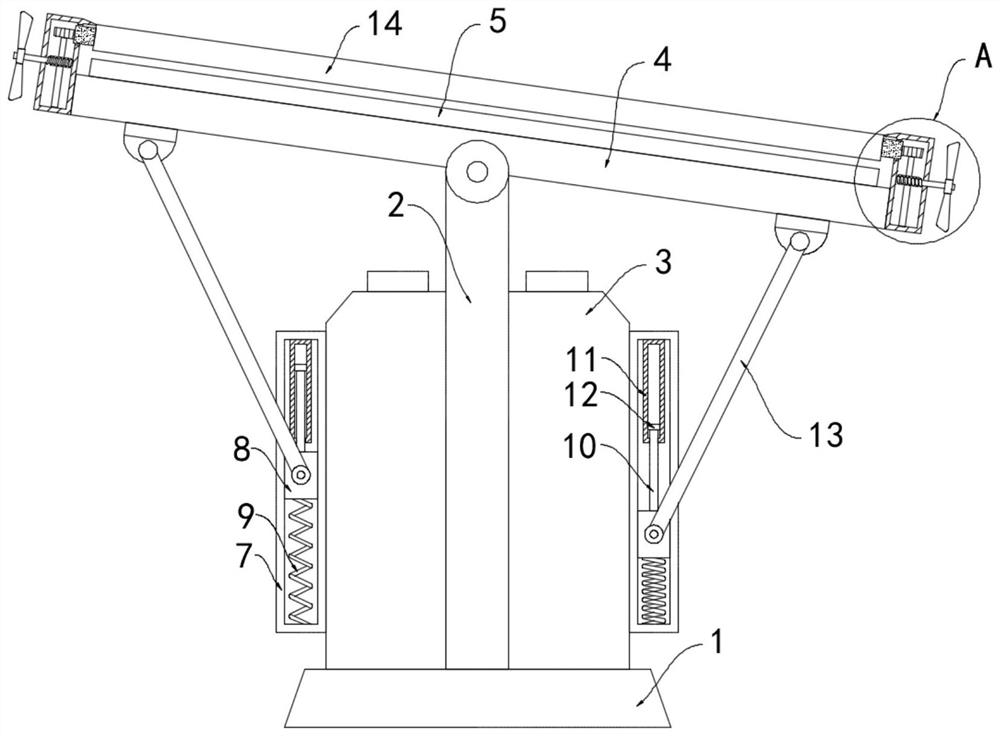
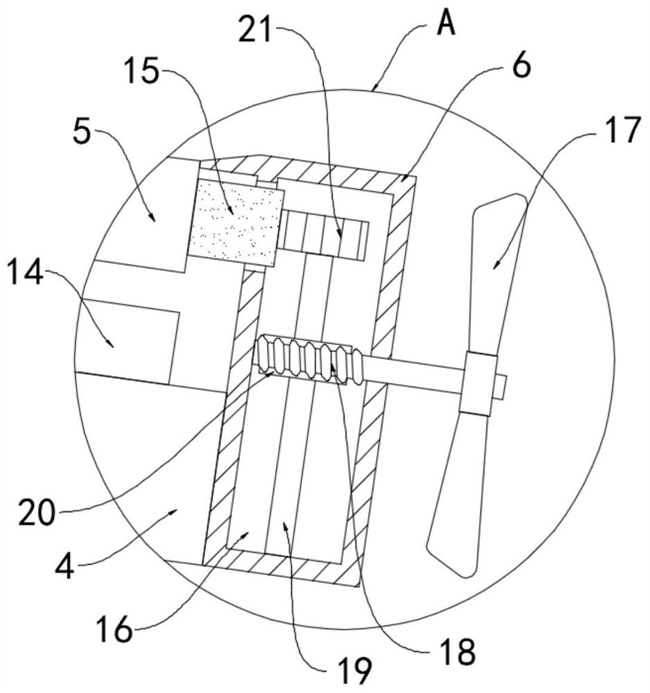
[0022] like Figure 2-3 As shown, the difference between this embodiment and Embodiment 1 is that: the upper surface of the photovoltaic panel 5 is provided with a dust-proof light-transmitting plate 14, and a gear ring 15 is fixedly sleeved on the peripheral side wall of the dust-proof light-transmitting plate 14, Fans 17 are arranged on both sides of the fence 6, and a transmission chamber 16 is arranged in the sidewall of the fence 6 close to the fan 17. The fan 17 is fixedly connected with a worm 18 coaxially, and the other end of the worm 18 extends into the transmission chamber 16 and Rotately connected with the enclosure 6, the bottom surface of the transmission cavity 16 is rotatably connected with a rotating shaft 19, and a worm wheel 20 and a gear 21 are coaxially installed outside the rotating shaft 19 successively, the worm wheel 20 meshes with the worm screw 18, and the gear 21 meshes with the ring gear 15.

[0023] In this embodiment, when the external wind blows...

Embodiment 3

[0025] The difference between this embodiment and Embodiment 1 lies in that the thermal expansion and contraction medium is mixed powder of silver bromide and copper oxide.

[0026] In this example, silver bromide can decompose under the catalytic conditions of light and copper oxide to generate bromine gas and expand in volume. The reaction equation is 2AgBr═2Ag+Br 2 , to promote the movement of the sealing slide plug 12, which is more sensitive to the light induction.


PUM


Abstract

The invention belongs to the field of new energy, and particularly relates to an intelligent adjustment charging station for a new energy automobile. The intelligent adjustment charging station comprises a base, a stand column and a charging pile body, the lower end of the stand column is fixedly connected with the upper surface of the base, the upper end of the stand column penetrates through thecharging pile body and is rotatably connected with a bearing plate, and a photovoltaic panel is installed on the upper surface of the bearing plate; a fence is fixedly connected to the peripheral side wall of the bearing plate, limiting sliding frames extending in the vertical direction are fixedly connected to the side walls of the two sides of the charging pile body, sliding blocks are slidablyconnected into the limiting sliding frames, and the lower ends of the sliding blocks are fixedly connected with the inner bottom faces of the limiting sliding frames through supporting springs; and the upper ends of the sliding blocks are fixedly connected with lifting rods, and transparent cylinders are fixedly installed on the inner top faces of the limiting sliding frames. According to the intelligent adjustment charging station, the photovoltaic panel on the bearing plate can always incline towards the sunlight irradiation direction, it is guaranteed that the photovoltaic panel fully receives sunlight irradiation, the utilization efficiency of light energy is improved, and meanwhile shielding can be better provided for the charging pile body.

Description

technical field [0001] The invention belongs to the field of new energy, and in particular relates to an intelligently adjusted charging station for new energy vehicles. Background technique [0002] The new energy vehicle charging station is one of the important tools for charging new energy vehicle equipment. With the development of technology and the enhancement of people's awareness of environmental protection, new energy is gradually replacing traditional petroleum energy for the automotive field. Therefore, the new energy vehicle charging station also increased. [0003] Most of the existing new energy vehicle charging stations are equipped with sun visors above the charging piles, or directly install photovoltaic panels instead of sun visors, which can not only play the role of shading and cooling, but also provide clean power for the charging piles. However, the traditional photovoltaic The board installation structure is fixed and cannot be flexibly adjusted accord...

Claims


Application Information

Patent Timeline
IPC IPC(8): B60L53/31B60L53/51H02S20/30H02S40/10
CPCB60L53/31B60L53/51H02S20/30H02S40/10Y02E10/50Y02T10/70Y02T10/7072Y02T90/12
Inventor 徐蕊吴川
Owner 徐蕊
Why Eureka
Try Eureka