
Textile printing and dyeing machine for textiles

A technology for printing and dyeing machines and textiles, which is applied in the direction of textiles and papermaking, textile material processing, and textile material detwisting devices, etc. It can solve the problems of cotton cloth being wrinkled in the drum and uneven extrusion of cotton cloth, so as to avoid wrinkles. Effect

Inactive Publication Date: 2020-12-08
北京弘福阁酒店管理有限公司
View PDF0 Cites 1 Cited by
  • Summary
  • Abstract
  • Description
  • Claims
  • Application Information

AI Technical Summary

Problems solved by technology

[0003] Based on the discovery by the inventors above, the existing textile printing and dyeing machine mainly has the following disadvantages, such as: the cotton cloth will become softer when it comes into contact with the dye, so that the cotton cloth will be gathered towards the middle under the drive of the roller, Causes the cotton cloth to appear wrinkled on the roller, resulting in uneven extrusion when the cotton cloth is extruded in the later stage

Method used


Image

  • Textile printing and dyeing machine for textiles
  • Textile printing and dyeing machine for textiles
  • Textile printing and dyeing machine for textiles

Examples

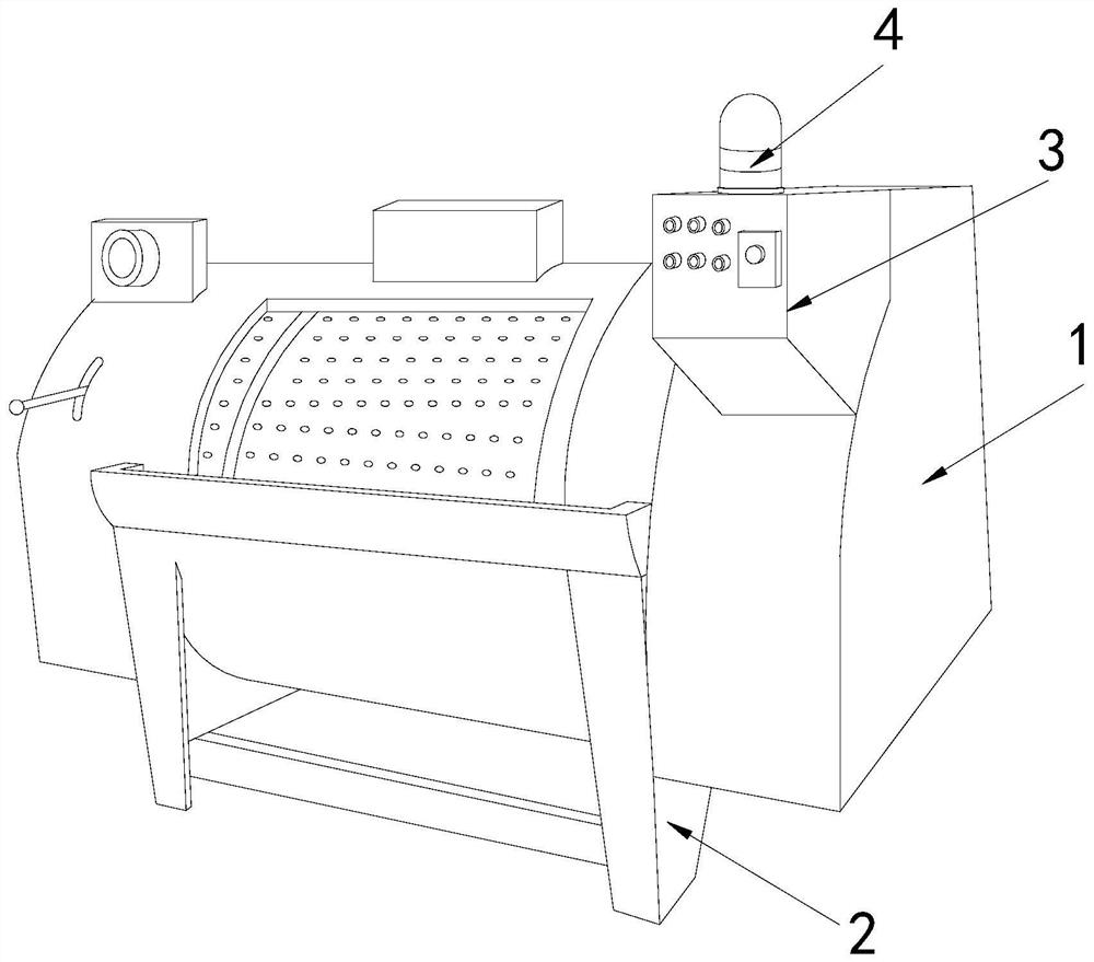
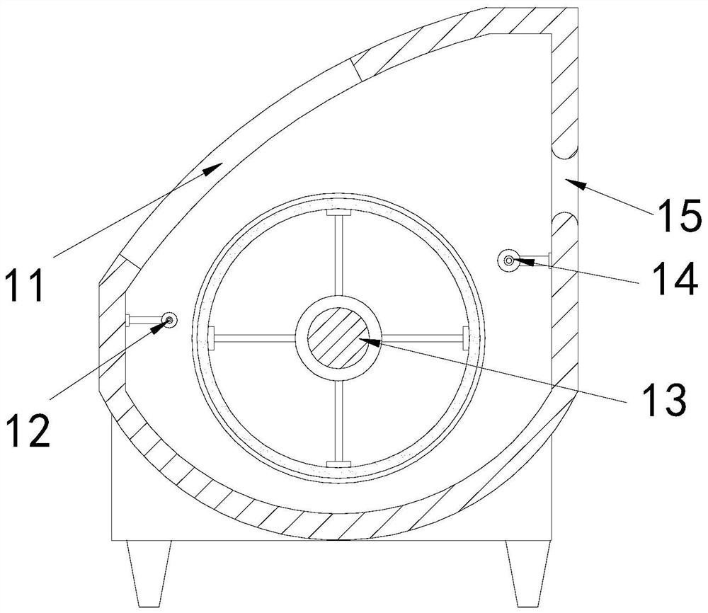
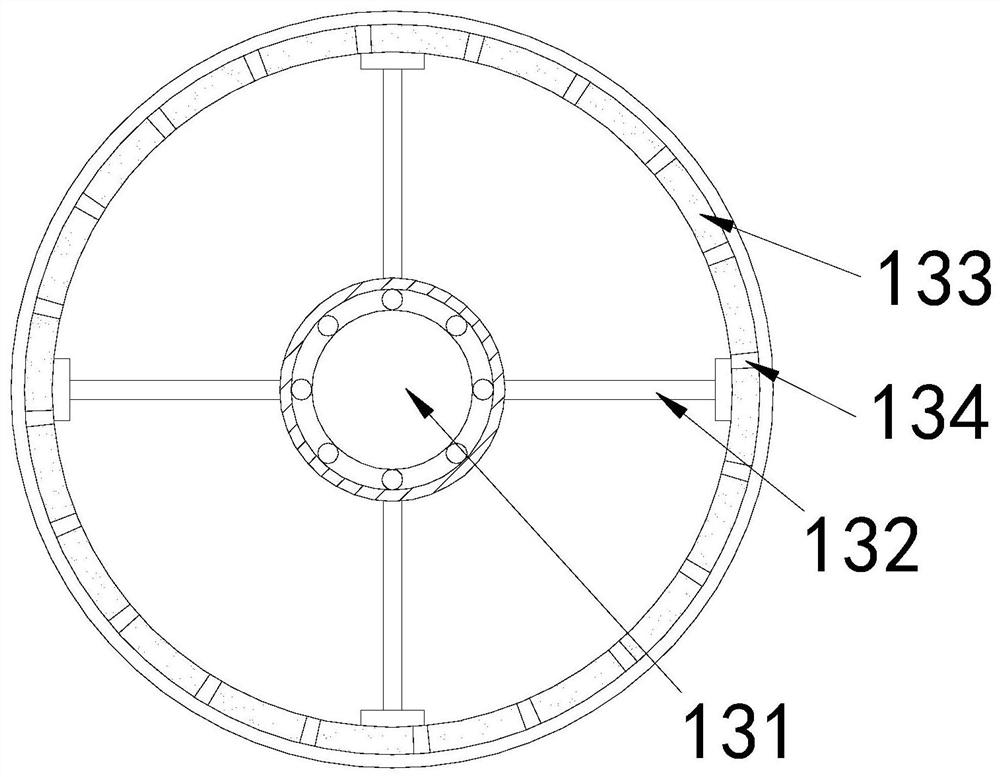

Embodiment 1

[0026] Example 1: Please refer to Figure 1-Figure 5 , the specific embodiments of the present invention are as follows:

[0027] Its structure includes its structure includes main body 1, supporting foot 2, control panel 3, warning light 4, and the bottom four ends of described main body 1 are respectively provided with a supporting foot 2, and described control panel 3 is positioned at the upper front end of main body 1, so The warning light 4 is installed on the top of the main body 1, and the main body 1 includes a feed port 11, a guide roller 12, a drum 13, a material extrusion roller 14, and a discharge port 15. The feed port 11 is arranged on the top of the main body 1. At the top, the guide roller 12 is installed at the bottom of the feed port 11, the roller 13 is engaged in the middle of the main body 1, and the extruding roller 14 is installed in the middle of the rear end of the main body 1. The discharge port 15 is arranged on the upper end of the extruding roller...

Embodiment 2

[0032] Example 2: Please refer to Figure 6-Figure 8 , the specific embodiments of the present invention are as follows:

[0033] The extruding roller 14 includes a supporting arm 141, an engaging block 142, a flow groove 143, and a collecting groove 144. The inner ends of both sides of the supporting arm 141 are engaged with an engaging block 142, and the engaging block 142 is embedded On both sides of the extruding roller 14, the flow groove 143 is arranged on the surface of the extruding roller 14, and the collection groove 144 is annular, and is arranged on the side end of the extruding roller 14. The width of the flow groove 143 is The extrusion roller 14 gradually narrows from the middle to both ends, which is beneficial to guiding the extruded dye.

[0034] The circulation groove 143 includes a rotating column b1, an annular body b2, a fixed rod b3, a feed groove b4, and a communication groove b5. The outer side of the rotating column b1 is provided with an annular bod...


PUM


Abstract

The invention discloses a textile printing and dyeing machine for textiles. The textile printing and dyeing machine structurally comprises a main body, supporting legs, a control panel and an alarm lamp, wherein one supporting leg is arranged at each of the four ends of the bottom of the main body, the control panel is located on the upper portion of the front end of the main body, the alarm lampis arranged at the top end of the main body, the main body comprises a feeding port, a guiding roller, a roller, a material squeezing roller and a discharging port, the material squeezing roller comprises a supporting arm, clamping blocks, a circulating groove and a concentrating groove, the circulating groove comprises a rotating column, a circular ring body, fixing rods, material passing groovesand communicating grooves, and each communicating groove comprises a groove body, a flow guiding block and a one-way hole. According to the textile printing and dyeing machine, the hole diameter of the material squeezing roller is arranged to be gradually reduced from the middle to the two ends, so that when the material squeezing roller drives cotton cloth to operate, the cotton cloth can be expanded towards the two ends, and the situation that the dye is not uniformly squeezed out due to wrinkles of the cotton cloth in the material squeezing roller is avoided.

Description

technical field [0001] The invention relates to the field of textiles, in particular to a textile printing and dyeing machine for textiles. Background technique [0002] At present, the printing and dyeing of cotton cloth mainly consists of dyeing, printing, finishing, washing and other processes. It is a relatively mature process. The cotton cloth printed and dyed through the above process has rich colors and high color fastness. After printing and dyeing, the cotton cloth can still maintain good softness. , during the dyeing process, it is necessary to place the dyed cotton cloth on the roller of the printing and dyeing machine, and then the roller drives the cotton cloth to soak in the dye for dyeing. Since the cotton cloth has good water absorption, when the cotton cloth is soaked in the dye, When the drum is rotated for winding, the dye attached to the cotton cloth will drip freely, so the lonely roller is needed to squeeze the dye in the cotton cloth. [0003] Based o...

Claims


Application Information

Patent Timeline
Patent Type & Authority Applications(China)
IPC IPC(8): D06B3/10D06B23/20D06B23/08
CPCD06B3/10D06B23/08D06B23/20
Inventor 洪乌柳
Owner 北京弘福阁酒店管理有限公司
Learn More