

A Slot Jet Film Cooling Structure for Turbine End Wall
A film cooling and air flow technology, which is applied to the supporting elements of the blade, machine/engine, engine function, etc., can solve the problem that the cooling efficiency of the turbine end wall is not significantly improved, the tangential velocity of the jet is not significantly improved, and the flow of cold air is reduced. To avoid air loss, improve coverage, and reduce momentum loss
- Summary
- Abstract
- Description
- Claims
- Application Information
AI Technical Summary
Problems solved by technology
Method used
Image

Examples
Embodiment 1
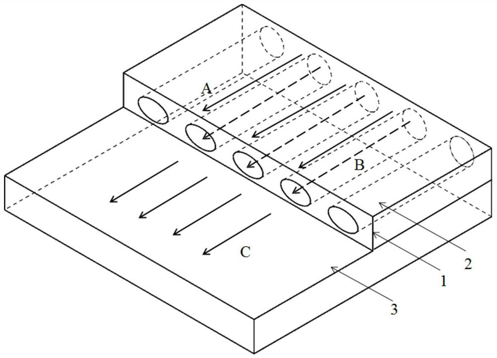
[0033] This embodiment is a cylindrical slot jet air film cooling structure on the end wall of the turbine vane. Arranged upstream of the turbine vane end wall 6 is a rearward stepped structure 5 , a jet air film hole 7 , and a slot air supply cavity 8 . It is characterized in that a slot jet air film hole 7 is arranged inside the backward step 5, wherein the outlet of the slot jet air film hole 7 is flush with the step surface of the backward step 5 and parallel to the plane 6 of the end wall of the turbine guide vane.
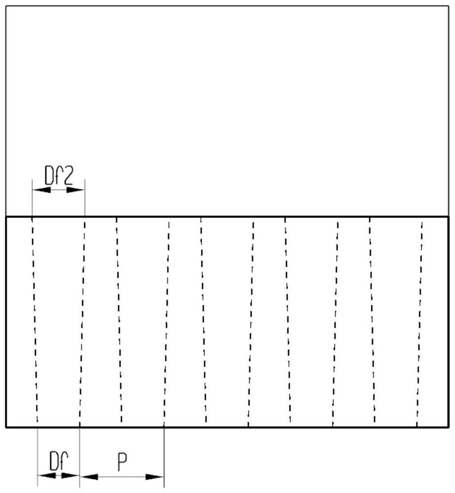
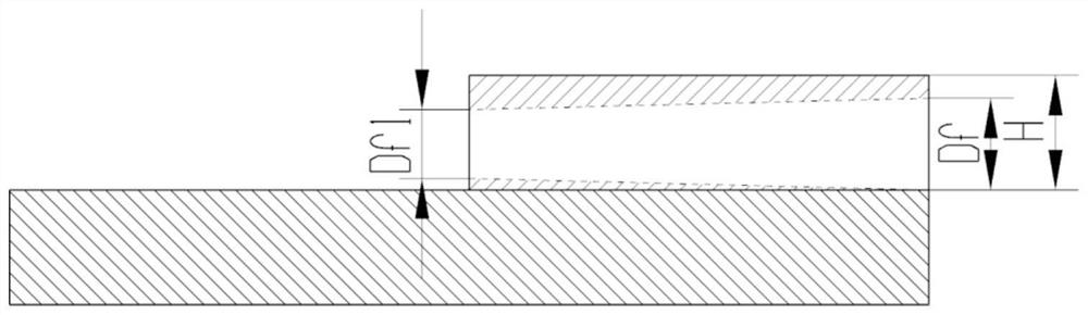
[0034] Jet film hole 2 inlet diameter D f 0.5mm, the short diameter of the air film hole 2 outlet D f1 is 0.5mm, and the long diameter of the outlet of air film hole 2 is D f2 0.5mm, the flow direction is the same as the mainstream.
[0035] The spanwise spacing P of the jet air film hole 2 is 2Df , whose value is 1mm.
[0036] The backward step height H is 2D f , whose value is 1mm.
[0037] The distance from the leading edge of the turbine guide vane ...
Embodiment 2
[0040] This embodiment is an expanding slot jet air film cooling structure on the end wall of the turbine guide vane. Arranged upstream of the turbine vane end wall 6 is a rearward stepped structure 5 , a jet air film hole 7 , and a slot air supply cavity 8 . It is characterized in that a slot jet air film hole 7 is arranged inside the backward step 5, wherein the outlet of the slot jet air film hole 7 is flush with the step surface of the backward step 5 and parallel to the plane 6 of the end wall of the turbine guide vane.
[0041] Jet film hole 2 inlet diameter D f 0.5mm, the short diameter of the air film hole 2 outlet D f1 is 0.5mm, and the long diameter of the outlet of air film hole 2 is D f2 0.7mm, the flow direction is the same as the mainstream.
[0042] The spanwise spacing P of jet air film holes 2 is 3D f , whose value is 1.5mm.
[0043] The backward step height H is 2D f , whose value is 1mm.
[0044] The distance from the leading edge of the turbine guide...
Embodiment 3
[0047] This embodiment is a tapered and diverging slot jet air film cooling structure on the end wall of the turbine vane. Arranged upstream of the turbine vane end wall 6 is a rearward stepped structure 5 , a jet air film hole 7 , and a slot air supply cavity 8 . It is characterized in that a slot jet air film hole 7 is arranged inside the backward step 5, wherein the outlet of the slot jet air film hole 7 is flush with the step surface of the backward step 5 and parallel to the plane 6 of the end wall of the turbine guide vane.
[0048] Jet film hole 2 inlet diameter D f 0.5mm, the short diameter of the air film hole 2 outlet D f1 is 0.35mm, and the long diameter of the outlet of air film hole 2 is D f2 0.7mm, the flow direction is the same as the mainstream.
[0049] The spanwise spacing P of jet air film holes 2 is 3D f , whose value is 1.5mm.
[0050] The backward step height H is 2D f , whose value is 1mm.
[0051] The distance from the leading edge of the turbine...
PUM
 Abstract
Description
Claims
Application Information