Noise reduction device and method for compressor
A compressor and noise reduction technology, which is applied in the field of compressor noise reduction, can solve the problems of insufficient medium and low frequency noise absorption capacity, untreated vibration of the cabin wall, and inability to absorb the noise of the internal pipeline and control system of the engine room, etc. Effects of reliability and validity
- Summary
- Abstract
- Description
- Claims
- Application Information
AI Technical Summary
Problems solved by technology
Method used
Image

Examples
Embodiment Construction
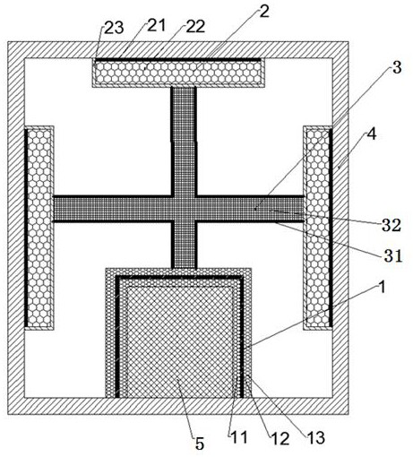
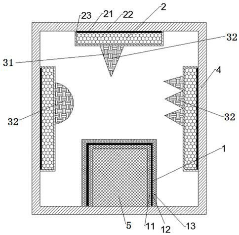
[0034] Combine below Figure 1~2 Embodiments of the present invention are described in detail.
[0035] The compressor noise reduction device includes a sound insulation cover 1, and the sound insulation cover 1 is arranged in the engine room 4 to wrap the compressor, and it is characterized in that it also includes a sound attenuation box arranged in the engine room 4 for absorbing noise and reducing the vibration of the wall plate of the engine room 4 2 and a sound-absorbing structure 3 arranged in the nacelle 4 for absorbing reflected sound waves, and the sound-absorbing structure 3 is arranged between the sound-absorbing box 2 and the sound-proof cover 1 .
[0036] The compressor noise reduction device described above includes a sound insulation cover 1, a noise reduction box 2 and a sound absorption structure 3. The sound insulation cover 1 is used to wrap the compressor to prevent the noise of the compressor from propagating to the inner cavity of the engine room, and th...
PUM
| Property | Measurement | Unit |
|---|---|---|
| Density | aaaaa | aaaaa |
| Density | aaaaa | aaaaa |
| Thickness | aaaaa | aaaaa |
Abstract
Description
Claims
Application Information