Eye movement control structure of robot and control system thereof
A technology of motion control and control structure, which is applied in the field of simulation robots, can solve the problems of difficult control of the precision of the expansion and contraction of the motion airbag, and the difficulty of air tightness requirements, and achieve the effect of soft motion, avoiding inconsistent rotation, and high degree of anthropomorphism
- Summary
- Abstract
- Description
- Claims
- Application Information
AI Technical Summary
Problems solved by technology
Method used
Image

Examples
Embodiment Construction
[0030] In order to make the purpose, principle and advantages of the present invention clearer, the present invention will be further described in detail below in conjunction with the accompanying drawings and embodiments. It should be understood that the specific embodiments described here are only used to explain the present invention, not to limit the present invention.
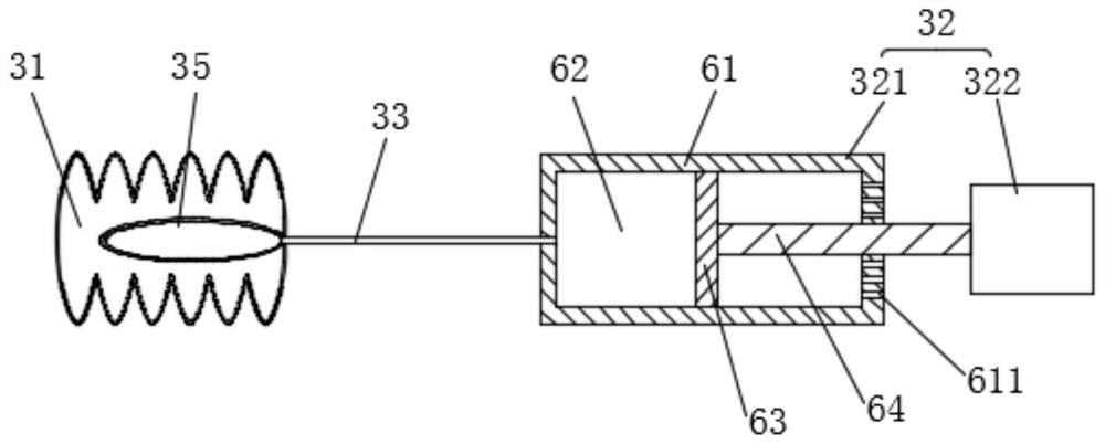
[0031] Such as figure 1 As shown, the eye control structure of a robot includes a control assembly, and the control assembly includes an action air bag 31, a liquid bag 35 and an electric hydraulic pump 32, and the action air bag 31 is a telescopic air bag that moves in one direction. A closed air cavity is formed inside the telescopic air bag; the liquid bag 35 is an elastic bag, and the liquid bag 35 is placed inside the action air bag 31, and one end of the liquid bag 35 is connected with a conduit 33; the electric hydraulic pump 32 includes a liquid-driven part 321 and motor drive part 322, the side o...
PUM
 Abstract
Description
Claims
Application Information