Eureka AIR delivers breakthrough ideas for toughest innovation challenges, trusted by R&D personnel around the world.

Permanent magnet motor control method suitable for low-speed direct-drive elevator

A control method and permanent magnet motor technology, which is applied in the direction of motor generator control, electronic commutation motor control, current controller, etc., can solve the problem of not being able to exert the optimal performance of permanent magnet motors, torque output, and dynamic response of low-speed performance. Fully adapt to the complex working conditions and high performance requirements of low-speed direct-drive hoists

Active Publication Date: 2020-12-08
LUOYANG CITIC HIC AUTOMATION ENG
View PDF7 Cites 8 Cited by
  • Summary
  • Abstract
  • Description
  • Claims
  • Application Information

AI Technical Summary

Problems solved by technology

[0004] Since the direct drive system does not have a reducer, the low-speed stability of the hoist is seriously affected by the cogging torque ripple of the permanent magnet motor under light load and the load disturbance under heavy load, which is equivalent to a sudden load at the moment the hoist is opened, and The system requires fast acceleration and deceleration operation. These working conditions have high requirements on the low-speed performance, overload capacity and dynamic performance of the frequency conversion control system; the traditional permanent magnet frequency conversion adopts i d = 0 control, this control method drops rapidly with the increase of load torque, and cannot fully adapt to the complex working conditions and high performance requirements of low-speed direct-drive hoists in terms of torque output, low-speed performance, and dynamic response. Can not play the best performance of permanent magnet motor

Method used


Image

  • Permanent magnet motor control method suitable for low-speed direct-drive elevator
  • Permanent magnet motor control method suitable for low-speed direct-drive elevator
  • Permanent magnet motor control method suitable for low-speed direct-drive elevator

Examples


Embodiment Construction

[0043] The following will clearly and completely describe the technical solutions in the embodiments of the present invention with reference to the accompanying drawings in the embodiments of the present invention. Obviously, the described embodiments are only some, not all, embodiments of the present invention. Based on the embodiments of the present invention, all other embodiments obtained by persons of ordinary skill in the art without making creative efforts belong to the protection scope of the present invention.

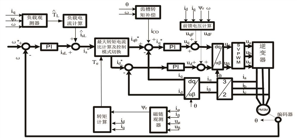
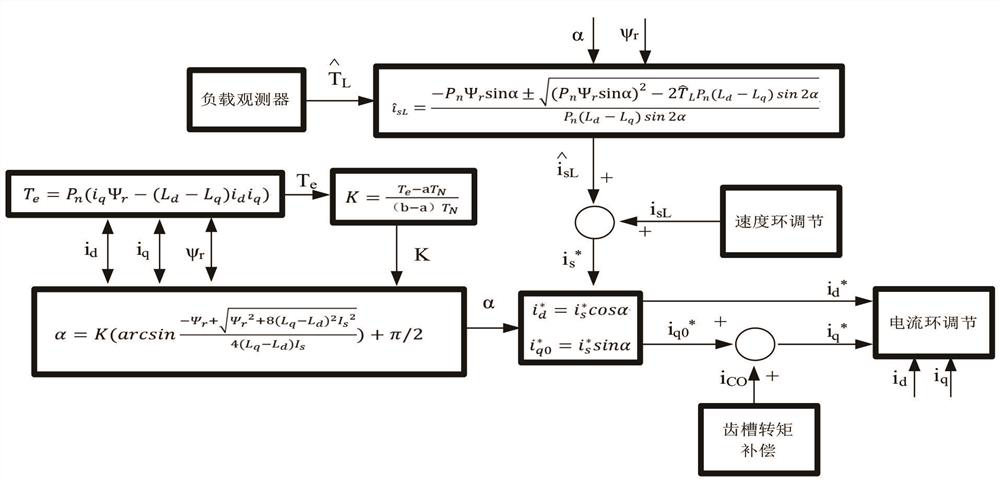
[0044] The present invention is a permanent magnet motor control method suitable for low-speed direct-drive hoists, and the present invention combines i d = 0 control and the advantages of maximum torque current ratio control, adding modules such as load observer, cogging torque compensation, and control mode switching to the traditional permanent magnet motor control system, i d = 0 control mode and maximum torque current ratio control mode switching process ...


PUM


Abstract

The invention belongs to the technical field of low-speed direct-drive elevator control, and particularly discloses a permanent magnet motor control method suitable for a low-speed direct-drive elevator. An id = 0 control mode and a maximum torque current ratio control mode are combined, the characteristic that id = 0 control current is completely decoupled during light load is utilized, cogging torque ripples are reduced by accurately compensating q-axis current, the operation stability of the elevator is improved, the cogging torque is smaller than the load torque after the load is increased, the influence on the system is weakened, at the moment, maximum torque current ratio control is adopted, the unit current torque output capacity is improved, smooth switching of the two control modes is achieved by controlling the included angle between the stator current and the rotor, the system torque response speed is greatly increased, and starting and stopping impact of the elevator is reduced. According to the invention, the permanent magnet motor can be controlled to realize strong torque output, good low-speed performance and rapid dynamic response, so that the low-speed direct-drive elevator system reaches the optimal working state.

Description

technical field [0001] The invention belongs to the technical field of low-speed direct-drive hoist control, and specifically discloses a permanent magnet motor control method suitable for low-speed direct-drive hoist. Background technique [0002] In order to improve system performance and efficiency, high-power hoists often adopt low-speed direct drive without reducer. The motor is a low-speed, high-torque motor that is directly connected to the main engine of the hoist. Therefore, the low-speed performance and torque output capability of the variable frequency drive system are required. Extremely high, in order to improve the load capacity of the system, electric excitation synchronous motors are mostly used. This type of motor has complex excitation systems, carbon brush slip rings and other equipment, and too many pole pairs will cause the motor size to be too large, generally only through Reduce the rated frequency to reduce the speed, which will greatly increase the c...

Claims


Application Information

Patent Timeline
IPC IPC(8): H02P21/02H02P21/04H02P21/22H02P21/20H02P6/28H02P6/10
CPCH02P21/02H02P21/04H02P21/22H02P21/20H02P6/28H02P6/10
Inventor 史光辉王正国邱玉林刘涛涛张念钰王浩狄辉辉武振华王浩然岳耀辉王璐宋海凤任高飞
Owner LUOYANG CITIC HIC AUTOMATION ENG
Why Eureka
Eureka Blog
Learn More