Environment-friendly treatment device for flue gas denitrification and nitrogen fertilizer co-production

An environmental protection treatment and denitrification technology, which is applied in the direction of cooling fluid circulation devices, combined devices, household refrigeration devices, etc., can solve problems such as the decline in working efficiency of electrostatic precipitators, process paralysis, flue gas denitration work, etc., and achieve the effect of convenient and fast structure

Inactive Publication Date: 2020-12-11
南昌升升科技有限公司
View PDF0 Cites 0 Cited by
  • Summary
  • Abstract
  • Description
  • Claims
  • Application Information

AI Technical Summary

Problems solved by technology

[0004] The purpose of the present invention is to provide an environmental protection treatment device for flue gas denitrification and co-production of nitrogen fertilizer, so as to solve the problem that the working efficiency of the electrostatic precipitator is reduced due to excessive flue gas temperature, and to further prevent the flow in the process from being blocked due to too many particles in the flue gas. Blockage, which leads to the paralysis of the whole process and cannot denitrify the flue gas in time, thus increasing the hazard probability of harmful gases containing nitrate entering the atmosphere

Method used


Image

  • Environment-friendly treatment device for flue gas denitrification and nitrogen fertilizer co-production
  • Environment-friendly treatment device for flue gas denitrification and nitrogen fertilizer co-production
  • Environment-friendly treatment device for flue gas denitrification and nitrogen fertilizer co-production

Examples


Embodiment Construction

[0019] The following will clearly and completely describe the technical solutions in the embodiments of the present invention with reference to the accompanying drawings in the embodiments of the present invention. Obviously, the described embodiments are only some, not all, embodiments of the present invention. Based on the embodiments of the present invention, all other embodiments obtained by persons of ordinary skill in the art without making creative efforts belong to the protection scope of the present invention.

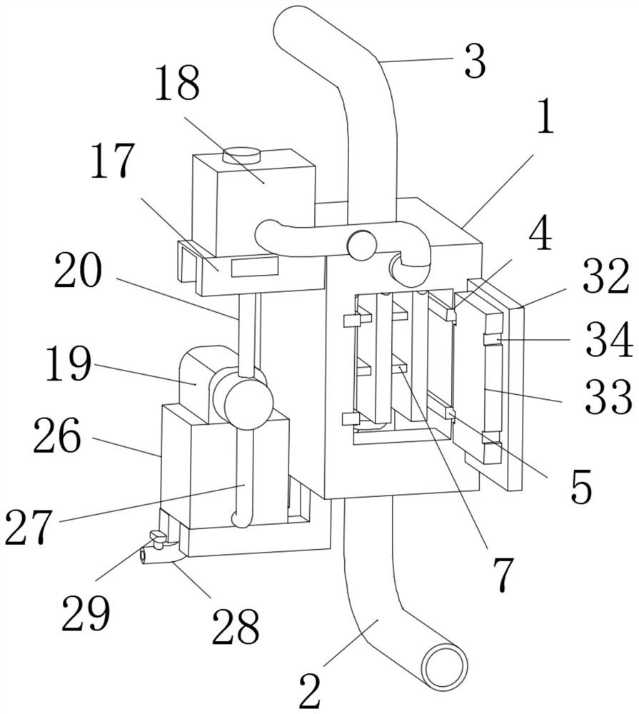
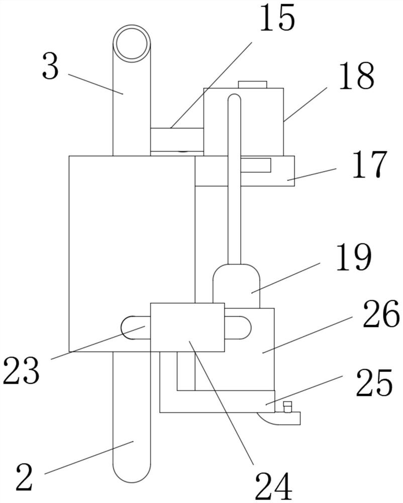
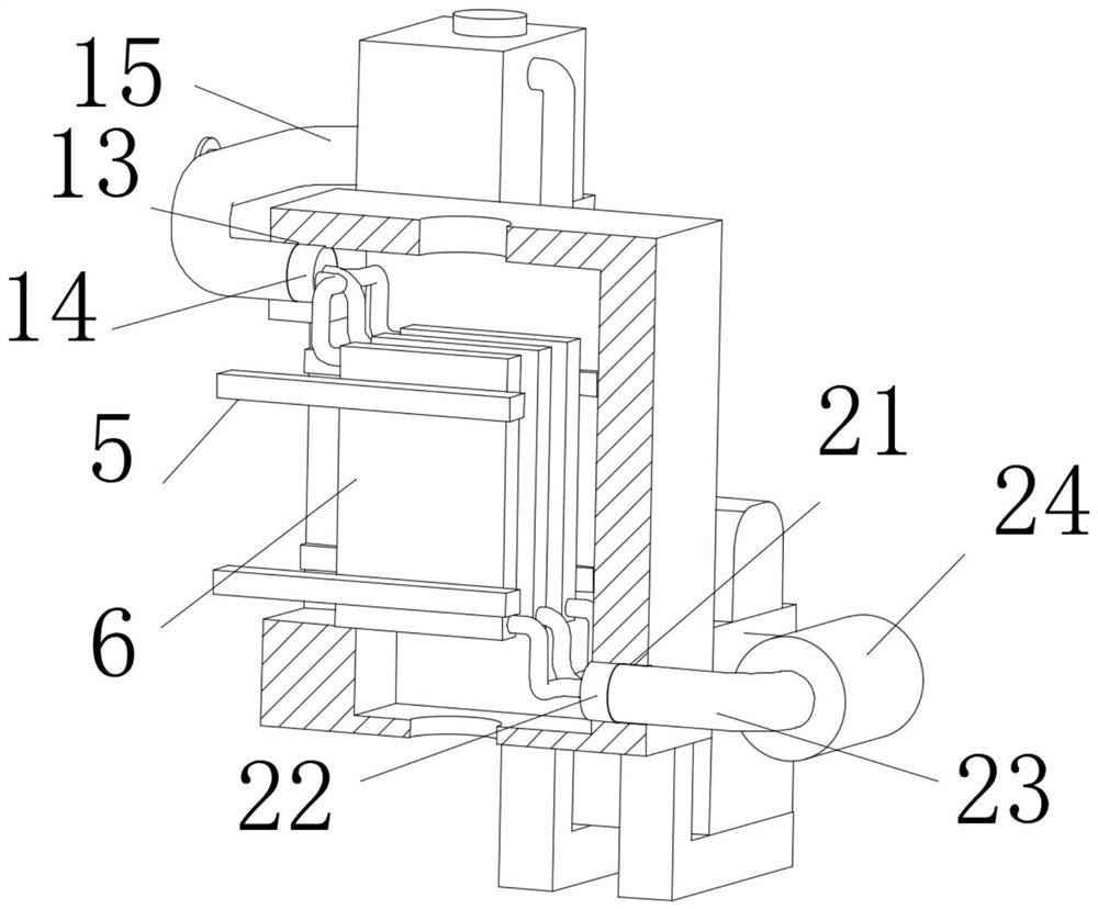
[0020] see Figure 1 to Figure 5 , the present invention provides a technical solution: the middle part of the bottom end of the filter box 1 is provided with a sealed and connected smoke inlet pipe 2, and the middle part of the top of the filter box 1 is provided with a sealed and connected smoke outlet pipe 3, and both sides of one end of the filter box 1 are symmetrically opened. The chute 4, and the square slider 5 is placed inside the square chute 4, and ...


PUM


Abstract

The invention relates to the technical field of flue gas denitrification environmental protection, and particularly relates to an environmental protection treatment device for flue gas denitrificationand nitrogen fertilizer co-production. A sealed smoke inlet pipe is arranged in the middle of the bottom end of a filter box in a penetrating mode, a sealed smoke outlet pipe is arranged in the middle of the top end of the filter box in a penetrating mode, and by arranging a regulating valve and a temperature measuring meter, the temperature in the filter box can be quickly observed by a worker,so that the temperature in the filter box can be adjusted, the worker can quickly master the temperature change more conveniently, and the temperature can be adjusted by quickly adjusting and controlling the water flow. Through the arrangement of the overall structure, a cooling cycle can be achieved on the whole, circulation and replacement of media in the cooling plate are kept, the temperaturein the filter box is kept in a replaced mode, and it is further avoided that the temperature of the media is higher than the temperature of flue gas all the time and the temperature cannot be guaranteed to be within a normal range. In addition, the structure is convenient and efficient and suitable for wide use.

Description

technical field [0001] The invention relates to the technical field of flue gas denitrification and environmental protection, in particular to an environmental protection treatment device for flue gas denitrification and co-production of nitrogen fertilizer. Background technique [0002] At present, among the pollutants that cause the above-mentioned atmospheric environmental problems, NOX occupies three items, which shows that it has a great impact on nature. NOX is not only the basis of nitric acid rain, but also one of the main substances that form photochemical smog and destroy the ozone layer. Strong toxicity, harmful to the human body, environment, ecology, and great damage to the social economy. Like SO2, NOX will fall to the ground through dry deposition and wet deposition in the atmosphere. The final destination is nitric acid Salt or nitric acid, nitric acid type acid rain is more harmful than sulfuric acid type acid rain, because it acidifies water bodies, leaches...

Claims


Application Information

Patent Timeline
IPC IPC(8): B01D50/00B01D46/42F25D17/02F25D19/00F25D29/00
CPCB01D46/4263B01D50/00F25D17/02F25D19/00F25D29/005
Inventor 不公告发明人
Owner 南昌升升科技有限公司
Why Eureka
Try Eureka