Method for forming special-shaped nozzle through single-engineering special-shaped part mold

A technology for mold forming and special-shaped parts, which is applied in the field of nozzle forming molds and processes, can solve problems such as pulling cracks and affect the yield of finished products, and achieve the effects of improving plasticity, improving yield and reducing stress concentration.

Pending Publication Date: 2020-12-11
马鞍山瑞恒精密制造有限公司
View PDF0 Cites 0 Cited by
  • Summary
  • Abstract
  • Description
  • Claims
  • Application Information

AI Technical Summary

Problems solved by technology

[0003] Ladle nozzles are generally pouring parts, but with technological progress, thin-walled parts are also used. Existing ladle nozzles such as figure 2 As shown, the forming of the special-shaped nozzle is realized through a series of stretching, but when the bottom rectangle is stretched during the stretching process, the cracking phenomenon occurs for a long time, which affects the yield

Method used


Image

  • Method for forming special-shaped nozzle through single-engineering special-shaped part mold
  • Method for forming special-shaped nozzle through single-engineering special-shaped part mold

Examples


Embodiment 1

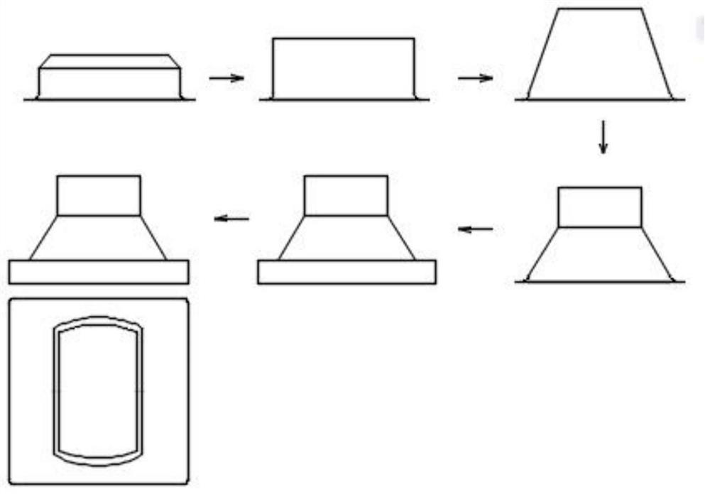
[0027] Such as figure 1 As shown, a method for forming a special-shaped nozzle with a single-engineering special-shaped mold, including six sets of molds, followed by a flange cylinder first drawing die, a flange cylinder second drawing die, a flange cone drawing die, and a flange Special-shaped stretching die, bottom rectangular stretching die and overall shaping die, the process steps are as follows:

[0028] Step 1. Initial stretching of the cylinder: Install the cut circular plate on the working platform of the press where the flange cylinder-drawing die is located, and perform initial flange rounding on the circular plate through the flange cylinder-drawing die. Once the cylinder is stretched, the half-finished product of the flange cylinder is obtained;

[0029] Step 2. Stretch the cylinder again: take off half of the finished flange cylinder and move it to the working platform of the press where the flange cylinder second stretching mold is located. Half of the finis...

Embodiment 2

[0036] On the basis of Example 1, the following improvements were made: in step five, preheat the semi-finished flange shaped semi-finished product before stretching to a temperature of 210°C.

[0037] In a further preferred solution of the present invention, after the stretching is completed, the bottom rectangular stretching mold is cooled before being separated from the bottom rectangular stretched semi-finished product, and the cooling rate is 13° C. every ten seconds.

[0038] The invention preheats the flange semi-finished product before stretching. When the preheating temperature is 150°C to 250°C, the plasticity of the workpiece can be greatly improved, the cracking phenomenon in the stretching process can be avoided, and the stretched finished product can be greatly improved. At the same time, cool down after stretching and reduce it by 10°C to 15°C every ten seconds to prevent recrystallization inside the workpiece and improve the stretching quality.

Embodiment 3

[0040] On the basis of Example 1, the following improvements are made: the temperature difference between the upper mold and the lower mold of the six sets of molds is 60°C to 130°C, preferably 124°C, and the upper mold and the corresponding lower mold are in a constant temperature state .

[0041] The invention utilizes the constant temperature between the upper mold and the lower mold of the six sets of molds and the temperature difference is 60°C to 130°C, which can reduce the transformation of internal austenite to martensite, effectively reduce stress accumulation, and avoid hardening of stainless steel materials become brittle, thus effectively improving the quality of the stretch.


PUM


Abstract

The invention discloses a method for forming a special-shaped nozzle through a single-engineering special-shaped part mold, and belongs to the technical field of nozzle forming molds and processes. Six sets of molds, namely a flange cylinder I drawing mold, a flange cylinder II drawing mold, a flange cone drawing mold, a flange special-shaped drawing mold, a bottom rectangular drawing mold and anintegral shaping mold in sequence are included. Cylinder primary drawing, secondary drawing, flange cone drawing, bottom rectangular drawing and integral shaping are achieved in sequence through the six molds. Especially, when bottom rectangular drawing is carried out, a tension fracture phenomenon is prone to occurring, and when the pressure change force is properly adjusted to be within the range of 20KN-25KN, the tension fracture phenomenon can be effectively avoided, and the finished product rate of products is greatly improved.

Description

technical field [0001] The invention relates to the technical field of nozzle forming dies and techniques, in particular to a method for molding a special-shaped nozzle with a single-engineering special-shaped part mold. Background technique [0002] Steel injection port, a steel injection port is set on the bottom side of the ladle, which allows molten steel to flow out from the inside of the ladle, so it is also called the ladle nozzle. [0003] Ladle nozzles are generally pouring parts, but with technological progress, thin-walled parts are also used. Existing ladle nozzles such as figure 2 As shown, the forming of the special-shaped nozzle is realized through a series of stretching, but when the bottom rectangle is stretched during the stretching process, the cracking phenomenon will occur for a long time, which will affect the yield. Contents of the invention [0004] The purpose of the present invention is to solve the deficiencies in the prior art, so a method for ...

Claims


Application Information

Patent Timeline
Patent Type & Authority Applications(China)
IPC IPC(8): B21D35/00
CPCB21D35/002
Inventor 郭玉山
Owner 马鞍山瑞恒精密制造有限公司
Why Eureka
Try Eureka