
Automobile shock absorber circulation part machining equipment

A technology of automobile shock absorbers and processing equipment, applied in metal processing equipment, metal processing, manufacturing tools, etc., can solve problems such as low work efficiency, inconvenient production, and no automatic assembly equipment for shock absorber circulation parts, and achieve work efficiency high effect

Active Publication Date: 2020-12-11
宁波云帆新能源科技有限公司
View PDF14 Cites 4 Cited by
  • Summary
  • Abstract
  • Description
  • Claims
  • Application Information

AI Technical Summary

Problems solved by technology

[0004] There is no automatic assembly equipment for the circulation parts of the shock absorber, and manual assembly is inefficient and inconvenient for production

Method used


Image

  • Automobile shock absorber circulation part machining equipment
  • Automobile shock absorber circulation part machining equipment
  • Automobile shock absorber circulation part machining equipment

Examples


Embodiment Construction

[0043] The following description serves to disclose the present invention to enable those skilled in the art to carry out the present invention. The preferred embodiments described below are only examples, and those skilled in the art can devise other obvious variations.

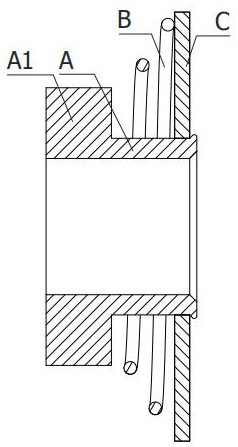
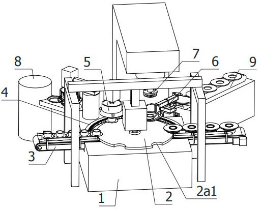
[0044] refer to figure 2 As shown in the figure, a processing equipment for circulation parts of automobile shock absorbers is applied to sequentially install the circulation valve spring B and the circulation valve plate C on the limit retaining ring A, and one end of the limit retaining ring A is provided with a rib A1, Processing equipment includes:

[0045] Workbench 1;

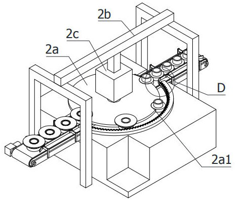
[0046] The step-rotating conveying assembly 2 includes a rotating disk 2a, which is installed on the workbench 1 in a vertical rotation axis, and the peripheral surface of the rotating disk 2a is evenly distributed along the axis for snapping ribs A1 and half-moon grooves 2a1;

[0047] The synchronous belt conveyor 3 is horizontall...


PUM


Abstract

The invention relates to the technical field of automatic assembly of automobile parts, in particular to automobile shock absorber circulation part machining equipment. The automobile shock absorber circulation part machining equipment comprises a workbench; a stepping rotary conveying assembly, wherein the stepping rotary conveying assembly comprises a rotary disc, the axis of the rotary disc isvertically and rotationally arranged on the workbench, and flanges and half-moon grooves used for clamping are evenly distributed in the circumferential surface of the rotary disc along the axis; a synchronous belt conveyor horizontally arranged at the bottom end of the stepping rotary conveying assembly in the radial direction of the stepping rotary conveying assembly; a semicircular limiting ring coaxially arranged on the outer edge of the stepping rotary conveying assembly; a first rotary loading mechanism and a second rotary loading mechanism, wherein the loading mechanisms are sequentially arranged on the outer edge of the semicircular limiting ring in the conveying direction of the stepping rotary conveying assembly; a riveting and pressing mechanism, wherein the working end of the riveting and pressing mechanism vertically faces the feeding end of a spring feeding mechanism and is arranged on the outer side of the workbench; and the spring feeding mechanism and a valve plate feeding mechanism, wherein the feeding mechanisms are arranged on the first rotary loading mechanism and the second rotary loading mechanism correspondingly, and the device is high in working efficiencyand precision.

Description

technical field [0001] The invention relates to the technical field of automatic assembly of automobile parts, in particular to a processing equipment for circulation parts of automobile shock absorbers. Background technique [0002] At present, the circulation part of the shock absorber in the prior art is not riveted with the limit retaining ring, which leads to complicated assembly, and the situation that the assembly of the spring and the valve plate is not in place is prone to occur. Low efficiency and high failure rate. [0003] Chinese patent CN200920197228.9 discloses an improved shock absorber flow part, which is mainly used on the shock absorber and mainly includes a limit stop ring, a flow valve plate and a flow valve spring. The outer diameter of the limit stop ring Cooperate with the inner diameter of the flow valve, the flow valve spring is set between the limit retaining ring and the flow valve, the limit retaining ring is provided with a riveting place on th...

Claims


Application Information

Patent Timeline
Patent Type & Authority Applications(China)
IPC IPC(8): B23P21/00B23P19/02B23P19/00
CPCB23P19/001B23P19/02B23P21/006
Inventor 朱陈芳
Owner 宁波云帆新能源科技有限公司
Learn More