Cable saddle rigidization structure and integral position-fixing and mounting method thereof

A cable saddle, integrated technology, applied in the direction of erecting/assembling bridges, bridge parts, bridges, etc., can solve the problems of long positioning time, restricting the construction progress of the cable tower, and high requirements for the positioning accuracy of the cable saddle. The effect of measuring the positioning time and avoiding the influence of bad weather

Inactive Publication Date: 2020-12-11
ZHEJIANG COMM CONSTR GRP CO LTD +1
View PDF12 Cites 2 Cited by
  • Summary
  • Abstract
  • Description
  • Claims
  • Application Information

AI Technical Summary

Problems solved by technology

[0004] The invention solves the defects in the prior art that the high-altitude positioning of the cable saddle takes a long time, requires high positioning accuracy of the cable saddle, and restricts the construction progress of the cable tower, and provides a rigid structure of the cable saddle and its overall positioning and installation method. The shaped steel frame and the cable saddle are consolidated after adjusting the elevation and space angle to form a cable saddle rigid body structure, fast positioning, high positioning accuracy, and no need for high-altitude positioning, which does not affect the cable tower construction and improves the overall construction progress

Method used


Image

  • Cable saddle rigidization structure and integral position-fixing and mounting method thereof
  • Cable saddle rigidization structure and integral position-fixing and mounting method thereof
  • Cable saddle rigidization structure and integral position-fixing and mounting method thereof

Examples


Embodiment

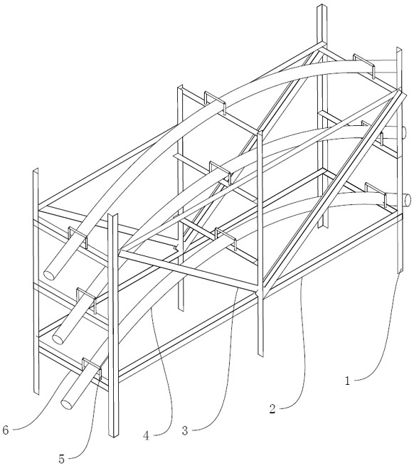
[0039] like figure 1 As shown, a cable saddle rigid body structure 10 includes a shaped steel frame body and a multi-layer cable saddle 4 installed on the shaped steel frame body. The multi-layer cable saddles are positioned with relative coordinates to ensure that the multi-layer The relative spatial angle between the cable saddles corresponds to the relative spatial angle of the cable saddles within the cable tower segment.

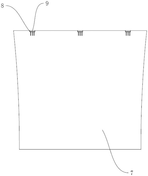
[0040] The shaped steel frame body includes a frame body vertical rod 1 corresponding to the position of the embedded part 8 of the cable tower segment, a positioning flat rod 6 connecting the frame body vertical rod horizontally, and a frame body flat rod 2 longitudinally connecting the frame body vertical rod And connect the frame body slanting bar 3 of the frame body vertical bar, the cable saddle is placed on the positioning flat bar and is positioned and fixed by the limit section steel 5.

[0041]The shaped steel frame has a cuboid structure as a...


PUM


Abstract

The invention relates to a cable saddle rigidization structure and an integral position-fixing and mounting method thereof. The cable saddle rigidization structure comprises a section steel frame bodyand multi-layer cable saddles mounted on the section steel frame body, wherein the position fixing of the multi-layer cable saddles relative to each other is achieved through relative coordinates; relative space angles of the multi-layer cable saddles are ensured to be in accordance with relative space angles of cable saddles in cable bent tower segments; the section steel frame body comprises frame body vertical rods corresponding to embedded parts in the cable bent tower segments in position, position-fixing horizontal rods transversely connected to the frame body vertical rods, and frame body horizontal rods longitudinally connected to the frame body vertical rods; the cable saddles are placed on the position-fixing horizontal rods; and the positions of the cable saddles are fixed through position-limiting section steel. The multi-layer cable saddles are controlled through the relative coordinates during rigidization, so that the relative positions of the multi-layer cable saddlesare guaranteed. The multi-layer cable saddles are integrally hoisted to the tower after rigidization and then controlled through absolute coordinates. The position fixing is fast, and the position fixing precision is high. In addition, position fixing performed aloft is not needed, and the construction of a cable bent tower is not affected, so that the overall construction progress is accelerated.

Description

technical field [0001] The invention belongs to the field of bridges, in particular to a cable saddle rigid body structure and an overall positioning and installation method thereof. Background technique [0002] With the continuous development of bridge technology, the appearance of low-tower cable-stayed bridges fills the intermediate state between girder bridges and cable-stayed bridges, and becomes a bridge between girder bridges (rigid) and cable-stayed bridges (flexible). The semi-rigid and semi-flexible structure has become the dominant bridge type with a span of 200-300 meters by virtue of its advantages of flexible design, simple construction, and beautiful appearance. In order to reduce the stress concentration on the main tower and improve the durability of the cables, and to facilitate cable replacement in the later stage, the form of the saddle is further optimized from a double-casing saddle to a split-tube saddle. [0003] The cable saddles are located on the...

Claims


Application Information

Patent Timeline
Patent Type & Authority Applications(China)
IPC IPC(8): E01D21/00E01D19/14
CPCE01D21/00E01D19/14
Inventor 何杨闽翁杨范远林叶建彬张立锐张红黎谢兰夫朱晨亮凌环宇姚正权喻红恩
Owner ZHEJIANG COMM CONSTR GRP CO LTD
Why Eureka
Try Eureka